AUDIO AND VISUAL SYSTEM (w/ Navigation System) Mute Signal Circuit between Stereo Component Amplifier and Telematics Transceiver
DESCRIPTION
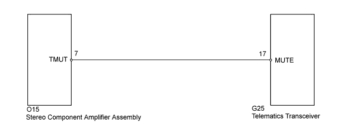
The telematics transceiver sends a mute signal to the stereo component amplifier assembly.
The stereo component amplifier assembly controls the volume according to the mute signal from the telematics transceiver.
WIRING DIAGRAM
INSPECTION PROCEDURE
Note
When replacing the telematics transceiver, perform vehicle contract setting (w/ G-BOOK System) Click here.
PROCEDURE
-
INSPECT TELEMATICS TRANSCEIVER
-
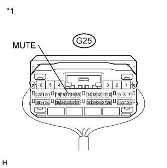
Text in Illustration *1 Component with harness connected
(Telematics Transceiver)
Measure the voltage according to the value(s) in the table below.
Standard Voltage Tester Connection Condition Specified Condition G25-17 (MUTE) - Body ground Power switch on (ACC), audio system is playing → Emergency call mode Above 2.5 V → Below 0.5 V
NG 
CHECK HARNESS AND CONNECTOR (STEREO COMPONENT AMPLIFIER ASSEMBLY - TELEMATICS TRANSCEIVER) Click here
OK 
PROCEED TO NEXT SUSPECTED AREA SHOWN IN PROBLEM SYMPTOMS TABLE Click here
-
-
CHECK HARNESS AND CONNECTOR (STEREO COMPONENT AMPLIFIER ASSEMBLY - TELEMATICS TRANSCEIVER)
-
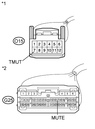
Text in Illustration *1 Front view of wire harness connector
(to Stereo Component Amplifier Assembly)
*2 Front view of wire harness connector
(to Telematics Transceiver)
Disconnect the stereo component amplifier assembly connector and telematics transceiver connector.
-
Measure the resistance according to the value(s) in the table below.
Standard Resistance Tester Connection Condition Specified Condition O15-7 (TMUT) - G25-17 (MUTE) Always Below 1 Ω O15-7 (TMUT) - Body ground Always 10 kΩ or higher
NG 
REPAIR OR REPLACE HARNESS OR CONNECTOR
OK 
-
-
INSPECT STEREO COMPONENT AMPLIFIER ASSEMBLY
-
Reconnect the stereo component amplifier assembly connector.
-
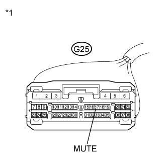
Text in Illustration *1 Front view of wire harness connector
(to Telematics Transceiver)
Measure the voltage according to the value(s) in the table below.
Standard Voltage Tester Connection Condition Specified Condition G25-17 (MUTE) - Body ground Power switch on (ACC) Above 2.5 V
NG
REPLACE STEREO COMPONENT AMPLIFIER ASSEMBLY Click here
OK
REPLACE TELEMATICS TRANSCEIVER Click here
-