ПЕРЕДНИЙ ПРИВОДНОЙ ВАЛ В СБОРЕ (для моделей с 1KR-FE) ПОВТОРНАЯ СБОРКА

-
INSTALL FRONT DRIVE SHAFT BEARING (for RH Side)
-
Install the front drive shaft bearing bracket hole snap ring into the inboard joint.
-
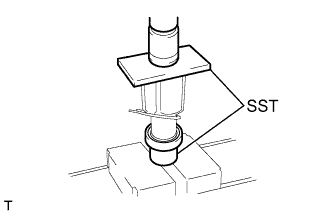
Using SST and a press, press in a new front drive shaft bearing.
- SST
- 09710-04081
- 09527-10011
Note
The bearing should be completely installed.
-
-
INSTALL FRONT DRIVE SHAFT HOLE SNAP RING RH (for RH Side)
-
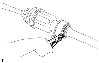
Using a snap ring expander, install a new snap ring.
-
-
INSTALL FRONT DRIVE SHAFT DUST COVER (for RH Side)
-
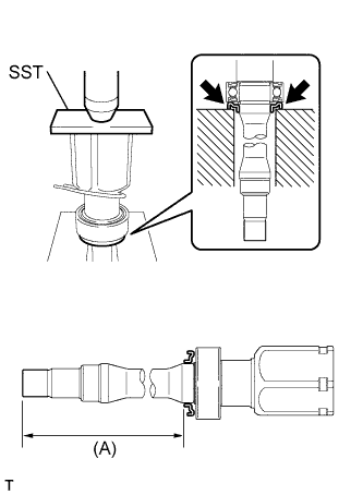
Using SST and a press, press a new dust cover into the inboard joint as shown in the illustration.
Standard Length (A) Transaxle Type Length CVT 276.5 +/- 0.5 mm
(10.89 +/- 0.020 in.)
Manual Transaxle 274.3 +/- 0.5 mm
(10.80 +/- 0.020 in.)
- SST
- 09527-10011
Note
-
Install the dust cover in the correct orientation.
-
Do not deform the dust cover.
-
-
INSTALL FRONT DRIVE SHAFT DUST COVER LH
-
Using SST and a press, press a new dust cover into the inboard joint until it is flush with the end.
- SST
- 09527-10011
Note
-
Install the dust cover in the correct orientation.
-
Do not deform the dust cover.
-
-
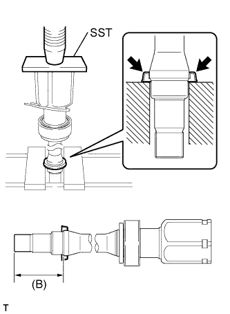
INSTALL FRONT DRIVE SHAFT DUST COVER RH
-
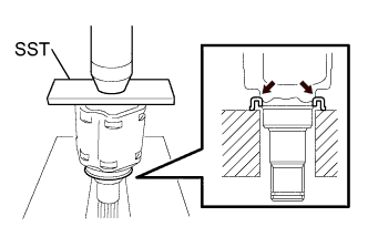
Using SST and a press, press a new dust cover into the inboard joint as shown in the illustration.
Standard Length (B) 73.2 +/- 0.3 mm (2.88 +/- 0.012 in.) - SST
- 09527-10011
Note
-
Install the dust cover in the correct orientation.
-
Do not deform the dust cover.
-
-
INSTALL FRONT DRIVE SHAFT HOLE SNAP RING LH
-
Install a new snap ring.
-
-
INSTALL FRONT AXLE OUTBOARD JOINT BOOT LH
-
Wrap the spline of the outboard joint shaft with protective tape.
-
Install new parts onto the outboard joint shaft in the following order.
Installation Order Order Part Name 1. Front No. 2 axle outboard joint boot clamp 2. Front axle outboard joint boot 3. Front axle outboard joint boot clamp -
Pack the joint portion of the outboard joint shaft and the outboard joint boot with grease.
Standard Quantity 86 to 96 g (3.0 to 3.4 oz.) -
Install the outboard joint boot onto the outboard joint shaft groove.
Note
Keep the groove free of grease.
-
-
INSTALL FRONT AXLE OUTBOARD JOINT BOOT RH
Tech Tips
Use the same procedure for the RH side as for the LH side.
-
INSTALL FRONT NO. 2 AXLE OUTBOARD JOINT BOOT CLAMP LH
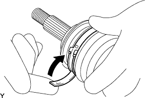
CAUTION:
Wear protective gloves to avoid injuries to your hands.
-
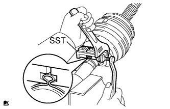
Install a new boot clamp onto the outboard joint boot and provisionally bend the lever.
Note
-
Check the band and the lever for any deformation before bending the lever.
-
Set the lever into the guide groove correctly and install the clamp as far into the inner side of the vehicle as possible.
-
-
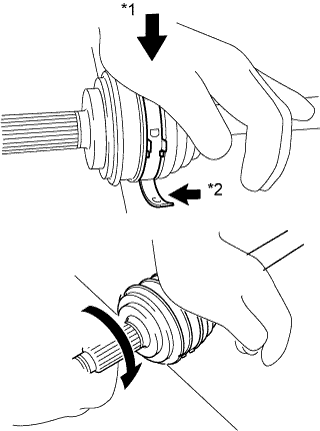
Text in Illustration *1 Weight *2 Contact Lean your weight on your hand and roll the outboard joint forward while pressing the outboard joint against the work plane. Roll the outboard joint and fold the lever until a click sound can be heard.
Note
-
Do not damage the deflector.
-
Make sure that the outboard joint is in direct contact with the work plane.
-
-
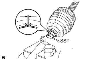
Using a plastic hammer, tap the buckle to fix it while adjusting the clearance between the lever and the groove to make the clearances between the buckle edge and the lever end even.
Note
Do not damage the outboard joint boot.
-
-
INSTALL FRONT NO. 2 AXLE OUTBOARD JOINT BOOT CLAMP RH
Tech Tips
Use the same procedure for the RH side as for the LH side.
-
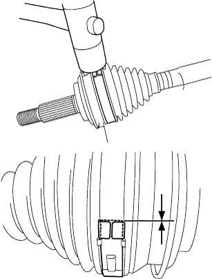
INSTALL FRONT AXLE OUTBOARD JOINT BOOT CLAMP LH
-
Place SST onto the boot clamp, press it against the boot and slightly tighten SST.
- SST
- 09521-24010
-
Fix SST and tighten it so that the clearance comes to within the specified range.
Standard Clearance 1.2 mm (0.047 in.) or less -
Remove SST.
-
Using SST, measure the clearance of the boot clamp as shown in the illustration.
- SST
- 09240-00020
Standard Clearance 1.2 mm (0.047 in.) or less Note
If the clearance is outside the specified range, retighten it.
-
-
INSTALL FRONT AXLE OUTBOARD JOINT BOOT CLAMP RH
Tech Tips
Use the same procedure for the RH side as for the LH side.
-
INSTALL FRONT DRIVE INBOARD JOINT ASSEMBLY LH
-
Install new parts onto the outboard joint shaft in the following order.
Installation Order Order Part Name 1. Front axle inboard joint boot clamp 2. Front axle inboard joint boot 3. Front No. 2 axle inboard joint boot clamp -
Fix the outboard joint shaft in a vise between aluminum plates.
Note
Do not overtighten the vise.
-
Remove the protective tape.
-
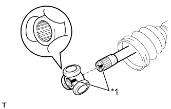
Text in Illustration *1 Matchmark Align the matchmarks and install the tripod joint onto the outboard joint shaft.
Note
Face the serrated side of the tripod joint outward and install it onto the outboard joint end.
-
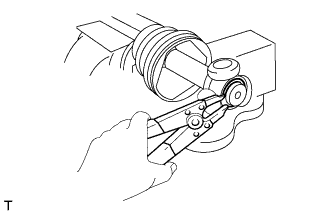
Using a brass bar and hammer, install the tripod joint.
Note
-
Do not hit the rollers.
-
Keep the tripod joint free of foreign matter.
-
-
Using a snap ring expander, install a new snap ring.
-
Pack the inboard joint with grease.
Standard Quantity Transaxle Type Quantity CVT 71 to 81 g (2.5 to 2.9 oz.) Manual Transaxle 112 to 122 g (4.0 to 4.3 oz.) -
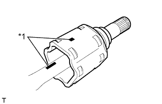
Text in Illustration *1 Matchmark Align the matchmarks and install the inboard joint onto the outboard joint shaft.
-
-
INSTALL FRONT DRIVE INBOARD JOINT ASSEMBLY RH
Tech Tips
Use the same procedure for the RH side as for the LH side.
-
INSTALL FRONT AXLE INBOARD JOINT BOOT LH
-
Install the inboard joint boot into the grooves of the inboard joint and outboard joint shaft.
Note
Keep the grooves free of grease.
-
-
INSTALL FRONT AXLE INBOARD JOINT BOOT RH
Tech Tips
Use the same procedure for the RH side as for the LH side.
-
INSTALL FRONT AXLE INBOARD JOINT BOOT CLAMP LH
-
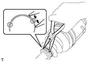
Using needle-nose pliers, engage the 2 claws and install the boot clamp as shown in the illustration.
Note
-
Do not damage the boot.
-
Do not deform the claw of the hook.
-
-
-
INSTALL FRONT AXLE INBOARD JOINT BOOT CLAMP RH
Tech Tips
Use the same procedure for the RH side as for the LH side.
-
INSTALL FRONT NO. 2 AXLE INBOARD JOINT BOOT CLAMP LH
-
Install the boot clamp onto the inboard joint boot.
-
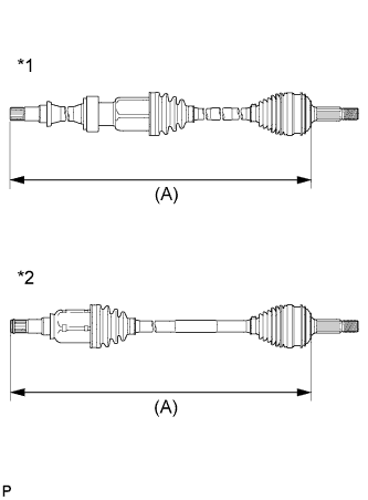
Text in Illustration *1 RH Side *2 LH Side Adjust dimension (A) until the drive shaft is within the specified length.
Dimension (A) Transaxle Type LH RH CVT 587.8 +/- 5 mm
(23.14 +/- 0.20 in.)
842.8 +/- 5 mm
(33.18 +/- 0.20 in.)
Manual Transaxle 587.4 +/- 5 mm
(23.13 +/- 0.20 in.)
840.2 +/- 5 mm
(33.08 +/- 0.20 in.)
-
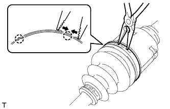
Using needle-nose pliers, engage the 2 claws and install the boot clamp as shown in the illustration.
Note
-
Do not damage the boot.
-
Do not deform the claw of the hook.
-
-
-
INSTALL FRONT NO. 2 AXLE INBOARD JOINT BOOT CLAMP RH
Tech Tips
Use the same procedure for the RH side as for the LH side.
-
INSPECT FRONT DRIVE SHAFT ASSEMBLY
-
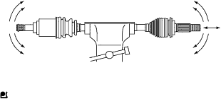
Check for noticeable looseness when turning the joint up and down, left and right, and in the thrust direction.
-
Check for cracks, damage and grease leakage on the boot joint.
Note
Keep the drive shaft level while moving it.
-
Text in Illustration *1 RH Side *2 LH Side Check for dimension (A).
Dimension (A) Transaxle Type LH RH CVT 587.8 +/- 5 mm
(23.14 +/- 0.20 in.)
842.8 +/- 5 mm
(33.18 +/- 0.20 in.)
Manual Transaxle 587.4 +/- 5 mm
(23.13 +/- 0.20 in.)
840.2 +/- 5 mm
(33.08 +/- 0.20 in.)
-