БЕССТУПЕНЧАТАЯ ТРАНСМИССИЯ В СБОРЕ УСТАНОВКА

-
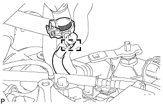
INSTALL TRANSMISSION CASE PLUG ASSEMBLY
Tech Tips
After replacing the continuously variable transaxle assembly, perform the following procedure.
-
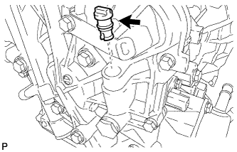
Apply a light coat of Toyota Genuine CVT fluid FE to the O-ring of a new transmission case plug assembly.
-
Install the transmission case plug assembly to the continuously variable transaxle assembly.
Note
Make sure that the O-ring is not cracked or moved out of place when installing the transmission case plug assembly.
-
-
INSTALL WIRE HARNESS CLAMP BRACKET
-
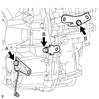
Install the 3 wire harness clamp brackets to the continuously variable transaxle assembly with the 3 bolts.
- Torque:
- Bolt A
- 29 N*m { 296 kgf*cm, 21 ft.*lbf }
- Bolt B
- 13 N*m { 130 kgf*cm, 9 ft.*lbf }
-
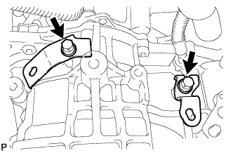
Install the 2 wire harness clamp brackets to the continuously variable transaxle assembly with the 2 bolts.
- Torque:
- 13 N*m { 130 kgf*cm, 9 ft.*lbf }
-
-
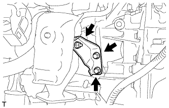
INSTALL NO. 1 TRANSMISSION CONTROL CABLE BRACKET
-
Install the No. 1 transmission control cable bracket to the continuously variable transaxle assembly with the 2 bolts.
- Torque:
- 12 N*m { 122 kgf*cm, 9 ft.*lbf }
-
-
INSTALL ENGINE MOUNTING BRACKET LH
-
Clean and degrease the bolts and the installation holes in the engine mounting bracket LH.
-
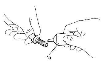
Text in Illustration *a Adhesive Apply adhesive to 2 or 3 threads on the ends of the 3 bolts.
Adhesive Toyota Genuine Adhesive 1324, Three Bond 1324 or equivalent Note
To prevent contamination by foreign matter, install immediately after applying adhesive.
-
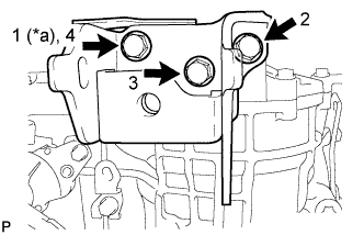
Text in Illustration *a Temporarily Tighten Install the engine mounting bracket LH to the continuously variable transaxle assembly with the 3 bolts in the order shown in the illustration.
- Torque:
- 64 N*m { 653 kgf*cm, 47 ft.*lbf }
-
-
INSTALL ENGINE MOUNTING STAY LH
-
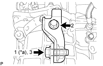
Text in Illustration *a Temporarily Tighten Install the engine mounting stay LH to the continuously variable transaxle assembly and the engine mounting bracket LH with the 2 bolts in the order shown in the illustration.
- Torque:
- 64 N*m { 653 kgf*cm, 47 ft.*lbf }
-
-
INSTALL CVT OIL PUMP TYPE T OIL SEAL
-
Ensure that there is no dirt or foreign matter on your hands, and then apply MP grease to the entire periphery of the lip of a new CVT oil pump type T oil seal.
-
Temporarily attach the CVT oil pump type T oil seal by pressing it onto the installation surface of the oil pump housing manually.
-
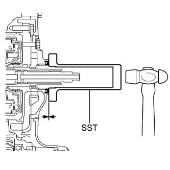
Clean the oil seal contact section of SST and the area around it.
-
Using SST, drive the CVT oil pump type T oil seal in evenly, until it is even with the side surface of the oil pump housing.
- SST
- 09309-36010
Drive in depth -0.2 to 0.2 mm (-0.00787 to 0.00787 in.) Note
-
Drive the CVT oil pump type T oil seal in gradually, while visually checking the parallelism.
-
After the installation, confirm that the CVT oil pump type T oil seal has been driven in as far as the side surface of the oil pump housing.
-
Wipe off any grease that has oozed out with your hand.
-
-
INSTALL TORQUE CONVERTER ASSEMBLY
-
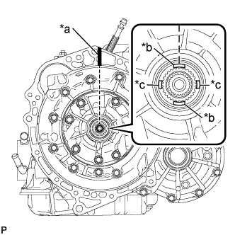
Text in Illustration *a Matchmark *b Wide Groove *c Narrow Groove Turn the front oil pump drive gear so that the groove is at the top and place a matchmark on the housing to indicate the position of the groove.
Note
-
Place the matchmark on the housing to indicate the position of the wide groove.
-
The matchmark position must be correct to prevent damage.
-
-
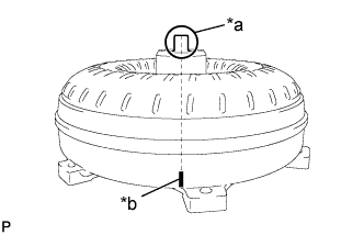
Text in Illustration *a Key *b Matchmark Place a matchmark on the torque converter assembly so that the position of its key is clearly indicated.
-
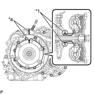
Text in Illustration *1 CVT Oil Pump Type T Oil Seal *a Matchmark Align the matchmark on the housing with the one on the torque converter assembly and engage the splines of the input shaft with the turbine runner splines.
Note
-
Maintain the torque converter assembly in a horizontal position when installing the input shaft.
-
Do not damage the CVT oil pump type T oil seal.
-
-
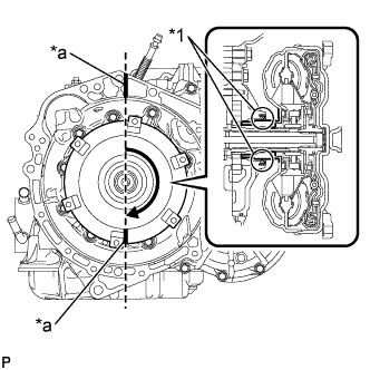
Text in Illustration *1 CVT Oil Pump Type T Oil Seal *a Matchmark Rotate the torque converter assembly approximately 180° and engage the splines of the stator shaft with the stator assembly.
Note
-
Maintain the torque converter assembly in a horizontal position when installing the stator shaft.
-
Do not damage the CVT oil pump type T oil seal.
-
-
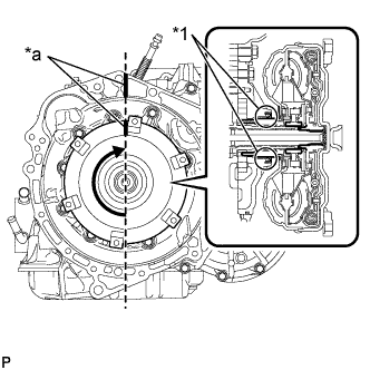
Text in Illustration *1 CVT Oil Pump Type T Oil Seal *a Matchmark Rotate the torque converter assembly approximately 180° again, align the matchmark on the torque converter assembly with the one on the housing and insert the key of the torque converter assembly into the groove of the oil pump drive gear.
Note
-
Do not push the torque converter assembly excessively when rotating it.
-
Maintain the torque converter assembly in a horizontal position when installing the input shaft and stator shaft.
-
Do not damage the CVT oil pump type T oil seal.
-
-
Clean the drive plate and torque converter setting bolt holes.
-
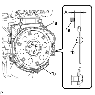
Text in Illustration *a Engine Surface *b Drive Plate Surface Using a vernier caliper and a straightedge, measure dimension "A" between the continuously variable transaxle assembly contact surface of the engine assembly*a and the torque converter assembly contact surfaces of the drive plate*b.
-
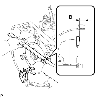
Using a vernier caliper and a straightedge, measure dimension "B" shown in the illustration and check that dimension "B" is more than dimension "A", which was measured in the previous step.
Standard distance B = A + 1 mm (0.0394 in.) or more Note
-
Make sure to deduct the thickness of the straightedge.
-
If the continuously variable transaxle assembly is installed to the engine assembly with the torque converter assembly not sufficiently inserted, the torque converter assembly may be damaged.
-
Do not include the thickness of the set block.
-
-
-
INSTALL CONTINUOUSLY VARIABLE TRANSAXLE ASSEMBLY
-
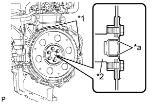
Text in Illustration *1 Knock Pin *2 Crankshaft *a Contacts Torque Converter Assembly Centerpiece Apply clutch spline grease to the circumference of the crankshaft that contacts the torque converter assembly centerpiece.
Clutch spline grease Toyota Genuine Clutch Spline Grease or equivalent Maximum grease amount Approximately 1 g (0.0353 oz) -
Confirm that the 2 knock pins are installed on the engine assembly and are not damaged.
-
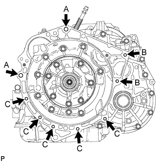
Install the continuously variable transaxle assembly to the engine assembly with the 9 bolts.
- Torque:
- Bolt A
- 64 N*m { 653 kgf*cm, 47 ft.*lbf }
- Bolt B
- 37 N*m { 377 kgf*cm, 27 ft.*lbf }
- Bolt C
- 39 N*m { 398 kgf*cm, 29 ft.*lbf }
Note
-
Make sure that the wire harness or similar items are not pinched between the contact surfaces.
-
Do not use excess force when installing the continuously variable transaxle assembly.
-
When mounting the continuously variable transaxle assembly to the engine assembly, make sure to securely fit the knock pins into the knock holes.
-
Check that the torque converter assembly rotates.
-
When tightening the bolts, be sure that the mating surfaces of the engine assembly and the continuously variable transaxle assembly are in close contact with one another.
Tech Tips
-
Bolt A: 45 mm (1.77 in.)
-
Bolt B: 45 mm (1.77 in.)
-
Bolt C: 35 mm (1.38 in.)
Bolt length
-
-
INSTALL DRIVE PLATE AND TORQUE CONVERTER SETTING BOLT
-
Clean and degrease the 6 drive plate and torque converter setting bolts.
-
Text in Illustration *a Adhesive Apply adhesive to 2 or 3 threads on the ends of the 6 drive plate and torque converter setting bolts.
Adhesive Toyota Genuine Adhesive 1324, Three Bond 1324 or equivalent Note
To prevent contamination by foreign matter, install immediately after applying adhesive.
-
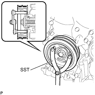
Use SST to hold the crankshaft pulley in place.
- SST
- 09960-10010 ( 09962-01000, 09963-01000 )
-
Install the 6 drive plate and torque converter setting bolts.
- Torque:
- 28 N*m { 286 kgf*cm, 21 ft.*lbf }
Note
-
First install the black-colored bolt, and then the remaining 5 silver-colored bolts.
-
Do not start the engine for at least 1 hour after installing the drive plate and torque converter setting bolts.
-
-
INSTALL STARTER ASSEMBLY
-
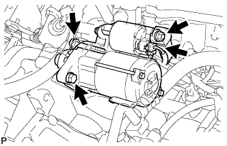
Install the starter assembly with the 2 bolts.
- Torque:
- 37 N*m { 377 kgf*cm, 27 ft.*lbf }
-
Connect the connector.
-
Connect the cable to terminal 30 with the nut.
- Torque:
- 9.8 N*m { 100 kgf*cm, 87 in.*lbf }
-
Close the terminal cap.
-
-
INSTALL ENGINE MOUNTING CONTROL BRACKET
-
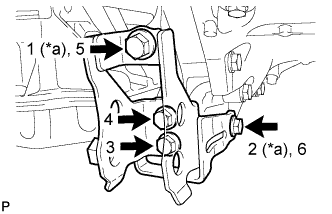
Text in Illustration *a Temporarily Tighten Install the engine mounting control bracket to the continuously variable transaxle assembly with the 4 bolts in the order shown in the illustration.
- Torque:
- 45 N*m { 459 kgf*cm, 33 ft.*lbf }
-
-
INSTALL ENGINE WIRE
-
Engage the 3 clamps and install the engine wire to the continuously variable transaxle assembly.
-
Connect the park/neutral position switch connector, transmission wire connector, transmission revolution sensor (NIN) connector and the transmission revolution sensor (NT) connector.
-
Install the engine wire to the continuously variable transaxle assembly with the bolt.
- Torque:
- 13 N*m { 130 kgf*cm, 9 ft.*lbf }
-
Engage the 5 clamps and install the engine wire to the continuously variable transaxle assembly.
-
Connect the oil pressure sensor connector and the transmission revolution sensor (NOUT) connector.
-
-
INSTALL WATER BY-PASS HOSE ASSEMBLY
-
Connect the 2 water by-pass hoses to the transmission oil cooler assembly with the 2 hose clips.
Text in Illustration 
Rear of Vehicle Note
Securely push the water by-pass hoses over each pipe fitting on the transmission oil cooler assembly until the hoses contact the rib on each pipe fitting.
-
Install the water by-pass hose assembly to the continuously variable transaxle assembly with the bolt.
- Torque:
- 29 N*m { 296 kgf*cm, 21 ft.*lbf }
-
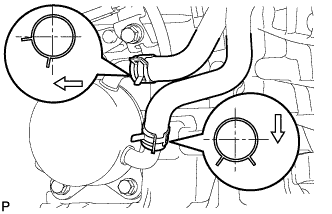
Engage the clamp and install the breather hose to the breather hose clamp.
Text in Illustration 
Paint Mark Tech Tips
-
Install the breather hose clamp so that the top end of it overlaps the painted area.
-
Install the breather hose clamp so that its protuberance is within the painted area.
-
-
-
INSTALL EXHAUST MANIFOLD
-
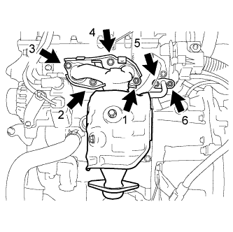
Place the 2 new gaskets and install the exhaust manifold, tightening the nuts and bolts in the sequence shown in the illustration.
- Torque:
- 28 N*m { 286 kgf*cm, 21 ft.*lbf }
-
-
INSTALL NO. 1 EXHAUST MANIFOLD HEAT INSULATOR
-
Install the No. 1 exhaust manifold heat insulator, tightening the nuts and bolts in the sequence shown in the illustration.
- Torque:
- 8.5 N*m { 87 kgf*cm, 75 in.*lbf }
-
-
INSTALL AIR FUEL RATIO SENSOR
-
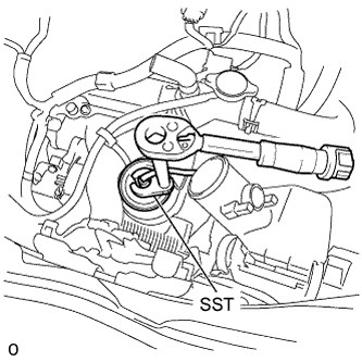
Using SST, install the air fuel ratio sensor to the exhaust manifold.
- SST
- 09224-00010
- Torque:
- without SST
- 44 N*m { 449 kgf*cm, 32 ft.*lbf }
- with SST
- 40 N*m { 408 kgf*cm, 30 ft.*lbf }
Note
-
The "with SST" torque value is effective when using SST with a fulcrum length of 30 mm (1.18 in.).
-
The "with SST" torque value is effective when using a torque wrench with a fulcrum length of 300 mm (11.81 in.) Click here.
-
This torque value is effective when SST is parallel to the torque wrench.
-
Install the wire harness clamp and connect the air fuel ratio sensor connector.
-
-
INSTALL MANIFOLD STAY
-
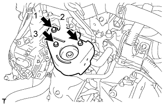
After temporarily tightening the manifold stay until the nut is firm against the exhaust manifold, fully tighten the manifold stay to the block with the 2 bolts and then fully tighten the nut on the exhaust manifold side.
- Torque:
- 24 N*m { 245 kgf*cm, 18 ft.*lbf }
-
-
INSTALL ENGINE ASSEMBLY WITH TRANSAXLE
-
RESET MEMORY (CVT initialization)