ПЕРВИЧНЫЙ ВАЛ ПОВТОРНАЯ СБОРКА

-
INSTALL FRONT INPUT SHAFT BEARING
-
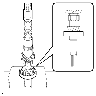
Using a press, install the front input shaft bearing onto the input shaft.
-
-
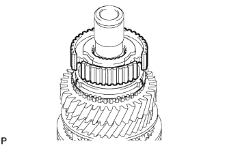
INSTALL 3RD GEAR NEEDLE ROLLER BEARING
-
Coat the 3rd gear needle roller bearing with gear oil and install it onto the input shaft.
-
-
INSTALL 3RD GEAR
-
Coat the 3rd gear with gear oil and install it onto the input shaft.
-
-
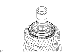
INSTALL NO. 3 SYNCHRONIZER RING
-
Coat the No. 3 synchronizer ring with gear oil and install it onto the 3rd gear.
-
-
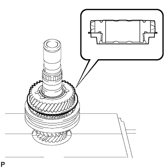
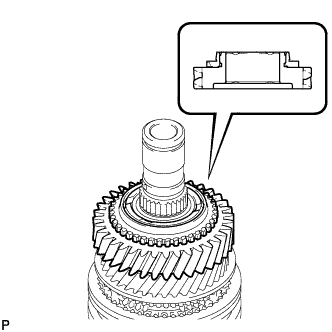
INSTALL NO. 2 TRANSMISSION CLUTCH HUB
-
Coat the No. 2 transmission hub with gear oil.
-
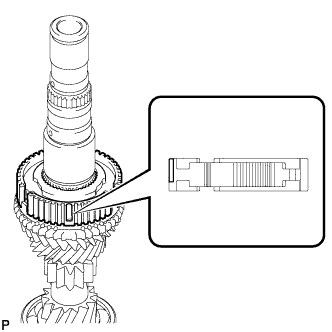
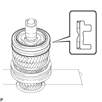
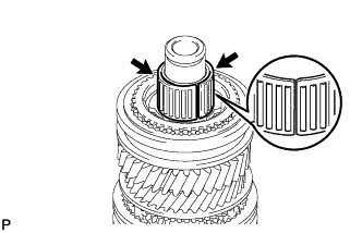
Install the No. 2 transmission clutch hub onto the input shaft.
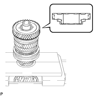
Note
Position the No. 2 transmission clutch hub correctly as shown in the illustration.
-
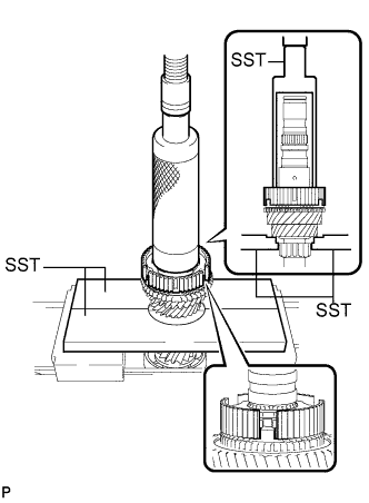
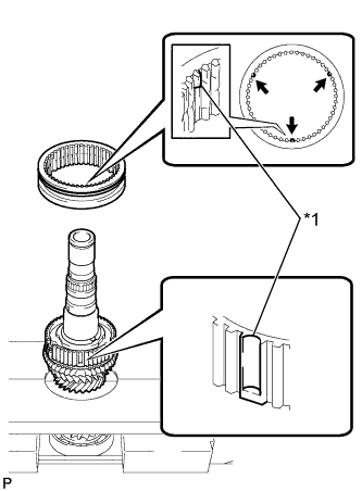
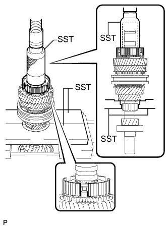
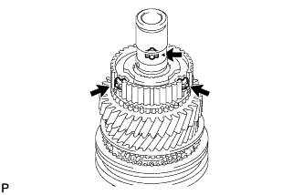
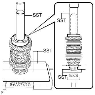
Using SST and a press, install the No. 2 transmission clutch hub onto the input shaft.
- SST
- 09527-21011
- 09316-60011 ( 09316-00011 )
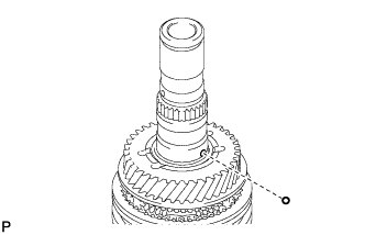
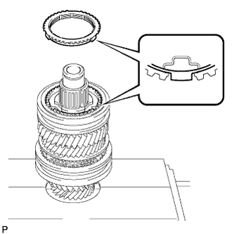
Note
When installing the No. 2 transmission clutch hub, align the protrusion of the No. 3 synchronizer ring with the cutout of the No. 2 transmission clutch hub.
-
-
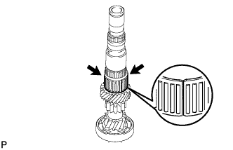
INSTALL NO. 2 CLUTCH HUB SETTING SHAFT SNAP RING
-
Select a snap ring that will allow minimal axial play.
Standard clearance 0.1 mm (0.00394 in.) or less Snap Ring Thickness Mark Thickness
mm (in.)
Mark Thickness
mm (in.)
0 2.27 (0.0894) 4 2.47 (0.0972) 1 2.32 (0.0913) 5 2.52 (0.0992) 2 2.37 (0.0933) 6 2.57 (0.1012) 3 2.42 (0.0953) 7 2.62 (0.1031) -
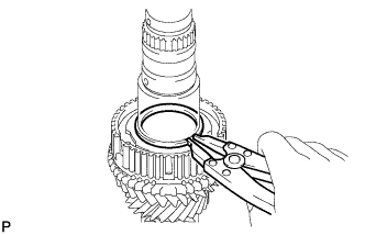
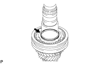
Using a snap ring expander, install the new No. 2 clutch hub setting shaft snap ring.
Note
-
Be sure to properly install the snap ring because it easily expands.
-
Do not damage the journal surface of the snap ring.
-
-
-
INSTALL NO. 2 SYNCHROMESH SHIFTING KEY
-
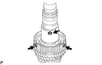
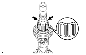
Install the 3 No. 2 synchromesh shifting keys to the No. 2 transmission clutch hub.
-
-
INSTALL NO. 2 TRANSMISSION HUB SLEEVE
-
Coat the No. 2 transmission hub sleeve with gear oil.
-
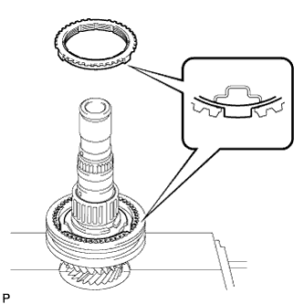
Text in Illustration *1 Align Install the No. 2 transmission clutch hub onto the No. 2 transmission hub sleeve.
Note
When installing the No. 2 transmission hub sleeve, align the protrusion of the No. 2 transmission hub sleeve with the cutout of the No. 2 transmission clutch hub.
-
-
INSTALL 4TH GEAR BEARING SPACER
-
Install the 4th gear bearing spacer onto the No. 2 clutch hub setting shaft snap ring.
-
-
INSTALL 4TH GEAR NEEDLE ROLLER BEARING
-
Coat the 4th gear needle roller bearing and 4th gear bearing spacer with gear oil and install them onto the No. 2 transmission clutch hub.
-
-
INSTALL OUTER 2ND SYNCHRONIZER RING
-
Coat the outer 2nd gear synchronizer ring with gear oil and install it onto the No. 2 transmission clutch hub.
Note
When installing the outer 2nd synchronizer ring, align the protrusion of the outer 2nd synchronizer ring with the cutout of the No. 2 transmission clutch hub.
-
-
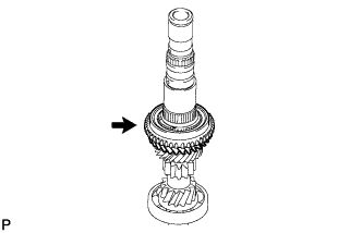
INSTALL 4TH GEAR
-
Coat the 4th gear with gear oil and install it onto the input shaft.
Note
Install the 4th gear as shown in the illustration.
-
-
INSTALL INNER 5TH GEAR BEARING RACE LOCK BALL
-
Coat the inner 5th gear bearing race lock ball with gear oil and install it onto the input shaft.
-
-
INSTALL INNER 5TH GEAR BEARING RACE
-
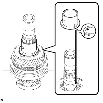
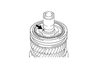
Coat the inner 5th gear bearing race with gear oil and install it onto the input shaft.
Note
Align the groove of the inner 5th gear bearing race with the ball.
-
-
INSTALL 5TH GEAR NEEDLE ROLLER BEARING
-
Coat the 5th gear needle roller bearing and inner 5th gear bearing race with gear oil and install them onto the input shaft.
-
-
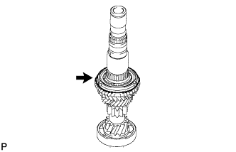
INSTALL 5TH GEAR
-
Coat the 5th gear with gear oil and install it onto the input shaft.
Note
Install the 5th gear as shown in the illustration.
-
-
INSTALL NO. 5 SYNCHRONIZER RING
-
Coat the No. 5 synchronizer ring with gear oil and install it onto the 5th gear.
-
-
INSTALL NO. 3 TRANSMISSION CLUTCH HUB
-
Coat the No. 3 transmission hub with gear oil.
-
Install the No. 3 transmission clutch hub onto the input shaft.
Note
Position the No. 3 transmission clutch hub correctly as shown in the illustration.
-
Using SST and a press, install the No. 3 transmission clutch hub onto the input shaft.
- SST
- 09309-37010
- 09527-21011
Note
When installing the No. 3 transmission clutch hub, align the protrusion of the No. 3 synchronizer ring with the cutout of the No. 5 transmission clutch hub.
-
-
INSTALL NO. 3 SYNCHROMESH SHIFTING KEY
-
Install the 3 No. 3 synchromesh shifting keys to the No. 3 transmission clutch hub.
-
-
INSTALL NO. 3 TRANSMISSION HUB SLEEVE
-
Coat the No. 3 transmission hub sleeve with gear oil.
-
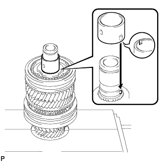
Install the No. 3 transmission hub sleeve onto the No. 3 transmission clutch hub.
Note
Install the No. 3 transmission hub sleeve as shown in the illustration.
-
-
INSTALL INNER 6TH GEAR BEARING RACE LOCK BALL
-
Coat the inner 6th gear bearing race lock ball with gear oil and install it onto the input shaft.
-
-
INSTALL INNER 6TH GEAR BEARING RACE
-
Coat the inner 6th gear bearing race with gear oil and install it onto the input shaft.
Note
Align the groove of the inner 6th gear bearing race with the ball.
-
-
INSTALL 6TH GEAR NEEDLE ROLLER BEARING
-
Coat the 6th gear needle roller bearing and inner 6th gear bearing race with gear oil and install them onto the input shaft.
-
-
INSTALL NO. 5 SYNCHRONIZER RING
-
Coat the No. 5 synchronizer ring with gear oil and install it onto the No. 3 transmission clutch hub.
Note
When installing the No. 5 synchronizer ring, align the protrusion of the No. 5 synchronizer ring with the cutout of the No. 3 transmission clutch hub.
-
-
INSTALL 6TH GEAR SUB-ASSEMBLY
-
Coat the 6th gear with gear oil and install it onto the input shaft.
Note
Install the 6th gear as shown in the illustration.
-
-
INSTALL REAR INPUT SHAFT RADIAL BALL BEARING
-
Using SST and a press, install the rear input shaft radial ball bearing onto the input shaft.
- SST
- 09527-21011
- 09608-04031
-
-
INSTALL REAR INPUT SHAFT BEARING SHAFT SNAP RING
-
Select a new snap ring that will allow minimal axial play.
Standard clearance 0.1 mm (0.00394 in.) or less Snap Ring Thickness Mark Thickness
mm (in.)
Mark Thickness
mm (in.)
A 1.65 (0.0650) H 2.00 (0.0787) B 1.70 (0.0669) J 2.05 (0.0807) C 1.75 (0.0689) K 2.10 (0.0827) D 1.80 (0.0709) L 2.15 (0.0846) E 1.85 (0.0728) M 2.20 (0.0866) F 1.90 (0.0748) N 2.25 (0.0886) G 1.95 (0.0768) P 2.30 (0.0906) -
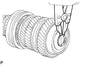
Using a snap ring expander, install the rear input shaft bearing shaft snap ring.
Note
-
Be sure to properly install the snap ring because it easily expands.
-
Do not damage the journal surface of the snap ring.
-
-
-
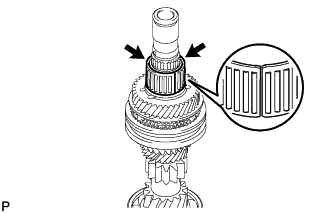
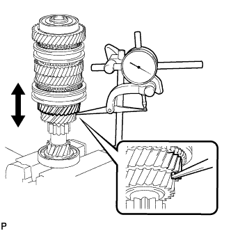
INSPECT 3RD GEAR RADIAL CLEARANCE
-
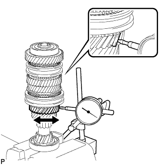
Using a dial indicator, measure the 3rd gear radial clearance.
Standard clearance 0.009 to 0.050 mm (0.000354 to 0.0197 in.) Maximum clearance 0.050 mm (0.0197 in.) If the clearance exceeds the maximum, replace the 3rd gear, 3rd gear needle roller bearing or input shaft.
-
-
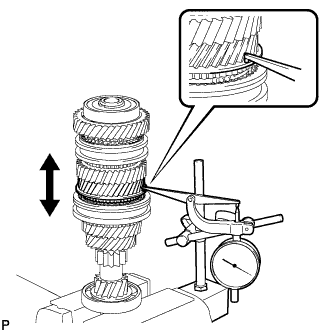
INSPECT 4TH GEAR RADIAL CLEARANCE
-
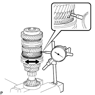
Using a dial indicator, measure the 4th gear radial clearance between the gear and shaft.
Standard clearance 0.009 to 0.050 mm (0.000354 to 0.0197 in.) Maximum clearance 0.050 mm (0.0197 in.) If the clearance exceeds the maximum, replace the 4th gear, 4th gear needle roller bearing or input shaft.
-
-
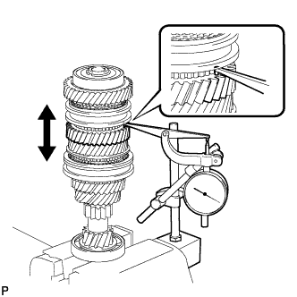
INSPECT 5TH GEAR RADIAL CLEARANCE
-
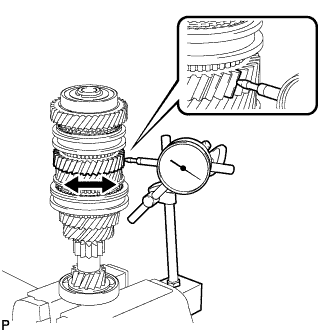
Using a dial indicator, measure the 5th gear radial clearance between the gear and shaft.
Standard clearance 0.009 to 0.045 mm (0.000354 to 0.00177 in.) Maximum clearance 0.045 mm (0.00177 in.) If the clearance exceeds the maximum, replace the 5th gear, 5th gear needle roller bearing, inner 5th gear bearing race or input shaft.
-
-
INSPECT 6TH GEAR RADIAL CLEARANCE
-
Using a dial indicator, measure the 6th gear radial clearance between the gear and shaft.
Standard clearance 0.009 to 0.075 mm (0.000354 to 0.00295 in.) Maximum clearance 0.075 mm (0.00295 in.) If the clearance exceeds the maximum, replace the 6th gear, 6th gear needle roller bearing, inner 6th gear bearing race or input shaft.
-
-
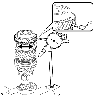
INSPECT 3RD GEAR THRUST CLEARANCE
-
Using a dial indicator, measure the 3rd gear thrust clearance.
Standard clearance 0.15 to 0.43 mm (0.00591 to 0.0169 in.) Maximum clearance 0.43 mm (0.0169 in.) If the clearance exceeds the maximum, replace the No. 2 transmission clutch hub, 3rd gear or input shaft.
-
-
INSPECT 4TH GEAR THRUST CLEARANCE
-
Using a dial indicator, measure the 4th gear thrust clearance.
Standard clearance 0.15 to 0.56 mm (0.00591 to 0.0220 in.) Maximum clearance 0.56 mm (0.0220 in.) If the clearance exceeds the maximum, replace the No. 2 transmission clutch hub, 4th gear or input shaft.
-
-
INSPECT 5TH GEAR THRUST CLEARANCE
-
Using a dial indicator, measure the 5th gear thrust clearance.
Standard clearance 0.15 to 0.43 mm (0.00591 to 0.0169 in.) Maximum clearance 0.43 mm (0.0169 in.) If the clearance exceeds the maximum, replace the No. 3 transmission clutch hub, 5th gear or input shaft.
-
-
INSPECT 6TH GEAR THRUST CLEARANCE
-
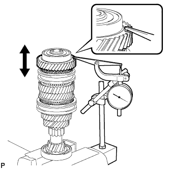
Using a dial indicator, measure the 6th gear thrust clearance.
Standard clearance 0.15 to 0.43 mm (0.00591 to 0.0169 in.) Maximum clearance 0.43 mm (0.0169 in.) If the clearance exceeds the maximum, replace the No. 3 transmission clutch hub, 6th gear or input shaft.
-