БЛОК МЕХАНИЧЕСКОЙ ТРАНСМИССИИ ПОВТОРНАЯ СБОРКА

-
PRECAUTION
Note
-
All disassembled parts should be cleaned before reassembly.
-
Coat all of the sliding and rotating surfaces with gear oil before reassembly, and check that they move smoothly after reassembly.
-
-
INSTALL FRONT DIFFERENTIAL CASE FRONT TAPERED ROLLER BEARING
-
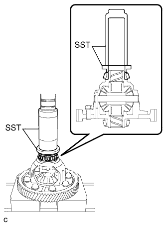
Using SST and a press, install a new front differential case front tapered roller bearing to the differential case assembly.
- SST
- 09309-37010
- 09506-35010
-
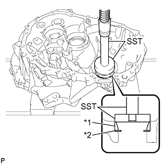
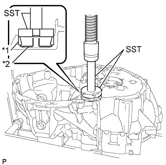
Text in Illustration *1 Front Differential Case Front Tapered Roller Bearing (Outer Race) *2 Front Differential Case Front Plate Washer Using SST and a press, install a new front differential case front tapered roller bearing (outer race) with the front differential case front plate washer to the front transaxle case.
- SST
- 09950-60020 ( 09951-00680 )
- 09950-70010 ( 09951-07200 )
-
-
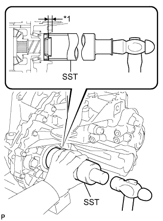
INSTALL FRONT DIFFERENTIAL CASE REAR TAPERED ROLLER BEARING
-
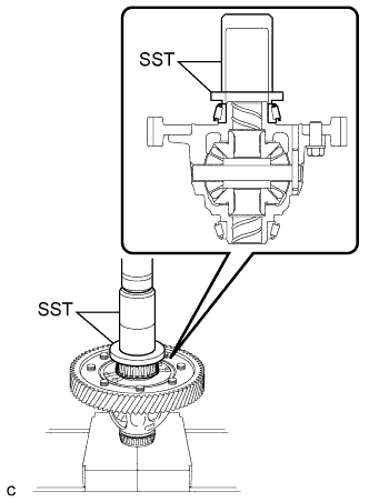
Using SST and a press, install a new front differential case rear tapered roller bearing to the differential case assembly.
- SST
- 09636-20010
- 09726-40010
-
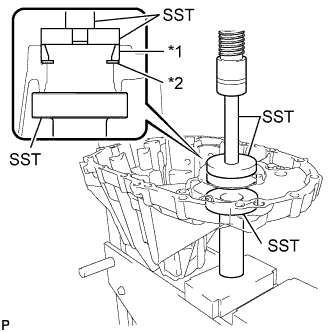
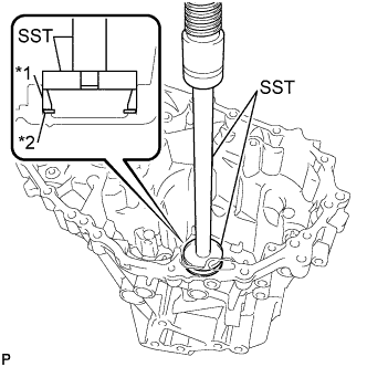
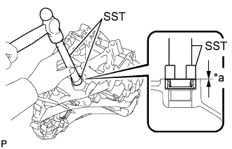
Text in Illustration *1 Front Differential Case Rear Tapered Roller Bearing (Outer Race) *2 Front Differential Case Rear Plate Washer Using SST and a press, install a new front differential case rear tapered roller bearing (outer race) with the front differential case rear plate washer to the manual transmission case.
- SST
- 09950-60020 ( 09951-00730 )
- 09950-70010 ( 09951-07100 )
Tech Tips
Use a plate washer of the same thickness as the removed one.
-
-
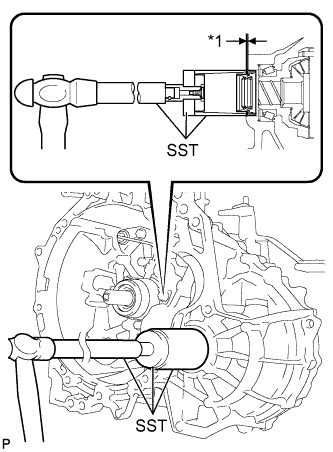
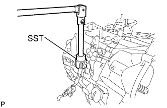
ADJUST DIFFERENTIAL SIDE BEARING PRELOAD
-
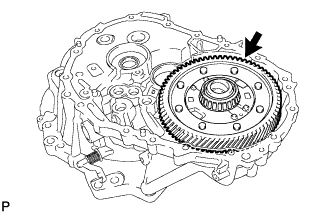
Coat the differential case assembly with gear oil and install it to the front transaxle case.
-
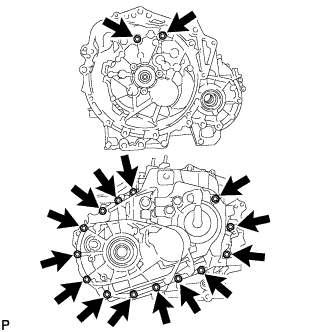
Install the manual transmission case with the 16 bolts.
- Torque:
- 29 N*m { 300 kgf*cm, 22 ft.*lbf }
-
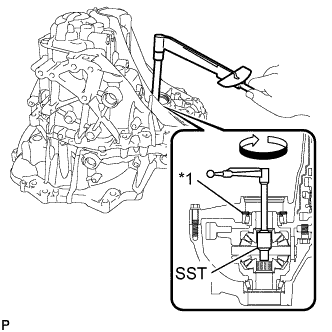
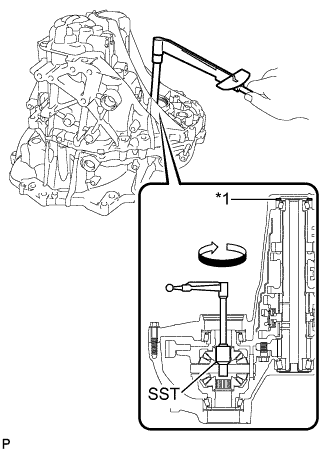
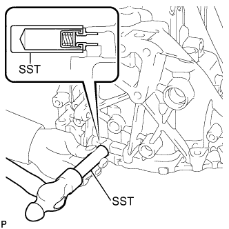
Text in Illustration *1 Front Differential Case Rear Plate Washer Using SST and a torque wrench, turn the differential case assembly clockwise and counterclockwise 2 or 3 times to allow the bearings to settle.
- SST
- 09564-32011
-
Using SST and a torque wrench, measure the preload.
- SST
- 09564-32011
Preload (at starting) New bearing 1.0 to 1.6 N*m (10 to 17 kgf*cm, 9 to 14 in.*lbf) Used bearing 0.8 to 1.3 N*m (9 to 13 kgf*cm, 8 to 12 in.*lbf) If the preload is out of specification, select a front differential case rear plate washer.
Front Differential Case Rear Plate Washer Thickness Mark Thickness
mm (in.)
Mark Thickness
mm (in.)
0 or 10 2.100 (0.0827) G or 26 2.500 (0.0984) 1 or 11 2.125 (0.0837) H or 27 2.525 (0.0994) 2 or 12 2.150 (0.0846) J or 28 2.550 (0.1004) 3 or 13 2.175 (0.0856) K or 29 2.575 (0.1014) 4 or 14 2.200 (0.0866) L or 30 2.600 (0.1024) 5 or 15 2.225 (0.0876) M or 31 2.625 (0.1033) 6 or 16 2.250 (0.0886) N or 32 2.650 (0.1043) 7 or 17 2.275 (0.0896) P or 33 2.675 (0.1053) 8 or 18 2.300 (0.0906) Q or 34 2.700 (0.1063) 9 or 19 2.325 (0.0915) R or 35 2.725 (0.1073) A or 20 2.350 (0.0925) S or 36 2.750 (0.1083) B or 21 2.375 (0.0935) T or 37 2.775 (0.1093) C or 22 2.400 (0.0945) U or 38 2.800 (0.1102) D or 23 2.425 (0.0955) V or 39 2.825 (0.1112) E or 24 2.450 (0.0965) W or 40 2.850 (0.1122) F or 25 2.475 (0.0974) - - Tech Tips
-
Select a thicker plate washer to increase the preload, or a thinner plate washer to decrease the preload.
-
Underlines are stamped to distinguish between marks "6" and "9".
-
Make a memo as the torque values will be needed for Output Shaft Bearing Preload.
-
Remove the 16 bolts and the manual transmission case.
-
Remove the differential case assembly from the front transaxle case.
-
-
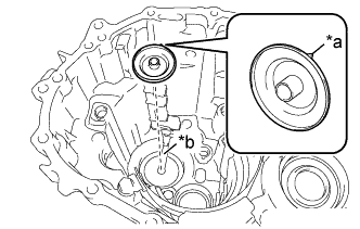
INSTALL OUTPUT SHAFT COVER
-
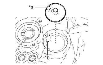
Text in Illustration *a Output Shaft Cover Key *b Front Transaxle Case Groove Install the output shaft cover to the front transaxle case.
Note
Insert the output shaft cover key into the front transaxle case groove.
-
-
INSTALL FRONT OUTPUT SHAFT BEARING
-
Text in Illustration *1 Front Output Shaft Bearing (Outer Race) *2 Output Shaft Cover Using SST and a press, install a new front output shaft bearing (outer race) to the front transaxle case.
- SST
- 09950-60010 ( 09951-00630 )
- 09950-70010 ( 09951-07100 )
-
-
INSTALL REAR OUTPUT SHAFT BEARING
-
Text in Illustration *1 Rear Output Shaft Bearing (Outer Race) *2 Rear Output Shaft Bearing Shim Using SST and a press, install a new rear output shaft bearing (outer race) with the rear output shaft bearing shim to the manual transmission case.
- SST
- 09950-60010 ( 09951-00590 )
- 09950-70010 ( 09951-07200 )
-
-
ADJUST OUTPUT SHAFT BEARING PRELOAD
-
Coat the differential case assembly with gear oil and install it to the front transaxle case.
-
Coat the output shaft assembly with gear oil and install it to the front transaxle case.
-
Install the manual transmission case with the 16 bolts.
- Torque:
- 29 N*m { 300 kgf*cm, 22 ft.*lbf }
-
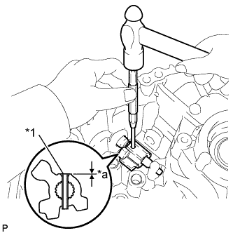
Text in Illustration *1 Rear Output Shaft Bearing Shim Using SST and a torque wrench, turn the differential case assembly clockwise and counterclockwise 2 or 3 times to allow the bearings to settle.
- SST
- 09564-32011
-
Using SST and a torque wrench, measure the preload. Calculate the rear output shaft bearing shim value using the following formula.
- SST
- 09564-32011
Formula (Differential side bearing preload + Output shaft bearing preload) - Differential side bearing preload = Output shaft bearing preload Preload (at starting) New bearing 3.3 to 5.6 N*m (34 to 58 kgf*cm, 29 to 50 in.*lbf) Used bearing 2.1 to 3.6 N*m (22 to 37 kgf*cm, 19 to 32 in.*lbf) If the preload is out of specification, select a rear output shaft bearing shim.
Rear Output Shaft Bearing Shim Thickness Mark Thickness
mm (in.)
Mark Thickness
mm (in.)
33 or 50 1.750 (0.0689) J or 72 2.300 (0.0906) 22 or 51 1.775 (0.0699) K or 73 2.325 (0.0915) 11 or 52 1.800 (0.0709) L or 74 2.350 (0.0925) 00 or 53 1.825 (0.0719) M or 75 2.375 (0.0935) 0 or 54 1.850 (0.0728) N or 76 2.400 (0.0945) 1 or 55 1.875 (0.0738) P or 77 2.425 (0.0955) 2 or 56 1.900 (0.0748) Q or 78 2.450 (0.0965) 3 or 57 1.925 (0.0758) R or 79 2.475 (0.0974) 4 or 58 1.950 (0.0768) S or 80 2.500 (0.0984) 5 or 59 1.975 (0.0778) T or 81 2.525 (0.0994) 6 or 60 2.000 (0.0787) U or 82 2.550 (0.1004) 7 or 61 2.025 (0.0797) V or 83 2.575 (0.1014) 8 or 62 2.050 (0.0807) W or 84 2.600 (0.1024) 9 or 63 2.075 (0.0817) X or 85 2.625 (0.1033) A or 64 2.100 (0.0827) Y or 86 2.650 (0.1043) B or 65 2.125 (0.0837) Z or 87 2.675 (0.1053) C or 66 2.150 (0.0846) ZZ or 88 2.700 (0.1063) D or 67 2.175 (0.0856) YY or 89 2.725 (0.1073) E or 68 2.200 (0.0866) XX or 90 2.750 (0.1083) F or 69 2.225 (0.0876) WW or 91 2.775 (0.1093) G or 70 2.250 (0.0886) VV or 92 2.800 (0.1102) H or 71 2.275 (0.0896) - - Tech Tips
-
Select a thicker bearing shim to increase the preload, or a thinner bearing shim to decrease the preload.
-
Underlines are stamped to distinguish between marks "6" and "9".
-
Remove the 16 bolts and the manual transmission case.
-
Remove the output shaft assembly from the front transaxle case.
-
Remove the differential case assembly from the front transaxle case.
-
-
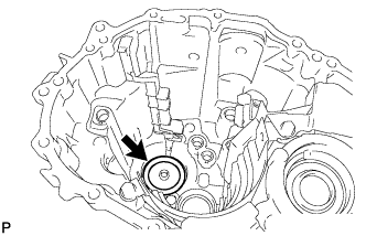
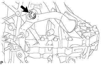
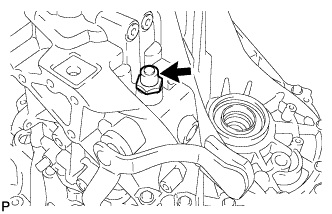
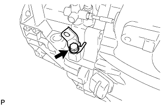
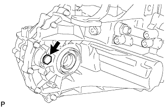
INSTALL BREATHER PLUG
-
Using SST and a hammer, install the breather plug to the manual transmission case.
- SST
- 09350-30020 ( 09350-07110 )
-
-
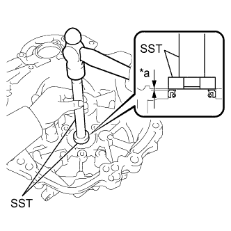
INSTALL OUTER SHIFT LEVER OIL SEAL
-
Text in Illustration *a Drive in Depth Using SST and a hammer, install a new outer shaft lever oil seal to the manual transmission case.
- SST
- 09950-60010 ( 09951-00260 )
- 09950-70010 ( 09951-07100 )
Standard depth 0.5 to 1.0 mm (0.0197 to 0.0393 in.) -
Coat the lip of the outer shaft lever oil seal with MP grease.
-
-
INSTALL OUTER NO. 1 SHIFT LEVER
-
Text in Illustration *1 Inner Shift Lever Slotted Spring Pin *a Drive in Depth Install the inner No. 1 shift lever, outer shift lever spacer and the outer No. 1 shift lever to the manual transmission case.
Standard depth -0.5 to 0.5 mm (-0.0196 to 0.0196 in.) -
Using a 5 mm pin punch and a hammer, install the inner shift lever slotted spring pin to the inner No. 1 shift lever.
-
-
INSTALL NO. 2 TRANSMISSION OIL SEPARATOR
-
Install the No. 2 transmission oil separator to the manual transmission case with the 2 bolts.
- Torque:
- 17 N*m { 173 kgf*cm, 13 ft.*lbf }
-
-
INSTALL MANUAL TRANSMISSION OIL SEPARATOR SUB-ASSEMBLY
-
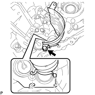
Install the manual transmission oil separator sub-assembly to the manual transmission case with the bolt.
- Torque:
- 17 N*m { 173 kgf*cm, 13 ft.*lbf }
Tech Tips
Make sure that the end tabs of the manual transmission oil separator sub-assembly are inserted in the grooves of the manual transmission case.
-
-
INSTALL NO. 1 TRANSMISSION OIL SEPARATOR
-
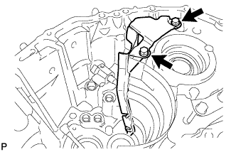
Install the No. 1 transmission oil separator to the manual transmission case with the 2 bolts.
- Torque:
- 17 N*m { 173 kgf*cm, 13 ft.*lbf }
Tech Tips
Make sure that the tip of the No. 1 transmission oil separator is inserted in the groove of the manual transmission case.
-
-
INSTALL NO. 1 OIL RECEIVER PIPE
-
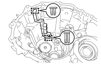
Engage the 2 guides and install the No. 1 oil receiver pipe to the manual transmission case.
Tech Tips
Make sure that the No. 1 oil receiver pipe fully contacts the manual transmission case.
-
-
INSTALL STRAIGHT PIN
-
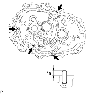
Text in Illustration *a Protrusion Height Using a plastic-faced hammer, tap in 4 new straight pins to the specified protrusion height.
Protrusion height 8.5 to 9.5 mm (0.335 to 0.374 in.)
-
-
INSTALL REVERSE RESTRICT PIN ASSEMBLY
-
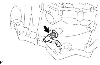
Install the reverse restrict pin assembly to the front transaxle case.
-
-
INSTALL TRANSMISSION OIL SEPARATOR
-
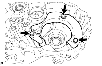
Install the transmission oil separator to the front transaxle case with the 3 bolts.
- Torque:
- 17 N*m { 173 kgf*cm, 13 ft.*lbf }
-
-
INSTALL FRONT TRANSAXLE CASE OIL SEAL
-
Text in Illustration *a Drive in Depth Using SST and a hammer, install a new front transaxle case oil seal to the front transaxle case.
- SST
- 09950-60010 ( 09951-00350 )
- 09950-70010 ( 09951-07100 )
Standard depth 0.9 to 1.9 mm (0.0355 to 0.0748 in.) -
Coat the lip of the front transaxle case oil seal with MP grease.
-
-
INSTALL TRANSMISSION MAGNET
-
Clean the transmission magnet and install it to the front transaxle case.
-
-
INSTALL INPUT SHAFT COVER
-
Text in Illustration *a Input Shaft Cover Key *b Manual Transmission Case Groove Install the input shaft cover to the manual transmission case.
Note
Insert the input shaft cover key into the manual transmission case groove.
-
-
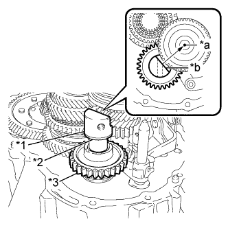
INSTALL REAR INPUT SHAFT BEARING SHIM
-
Install the rear input shaft bearing shim to the manual transmission case.
Note
Apply MP grease to the shim as necessary to prevent the shim from falling off the case during assembly.
-
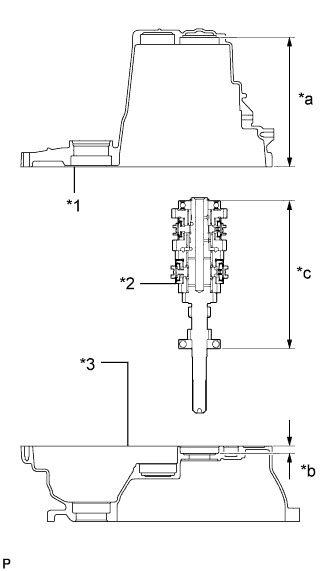
Text in Illustration *1 Manual Transmission Case *2 Input Shaft Assembly *3 Front Transaxle Case *a Dimension A *b Dimension B *c Dimension C Measure the distance between the end of the manual transmission case and the rear input shaft bearing shim (Dimension A).
-
Measure the distance between the end of the front transaxle case and the installation surface of the front input shaft bearing (Dimension B).
-
Measure the distance between both input shaft bearing outer races (Dimension C).
Note
Measure Dimension C with each bearing having no axial clearance.
-
Calculate the rear input shaft bearing shim value using the following formula.
Formula (Dimension A + Dimension B) - Dimension C - Rear input shaft bearing shim thickness = 0.02 to 0.14 mm (0.000788 to 0.00551 in.) If the thickness is out of specification, select a rear input shaft bearing shim.
Rear Input Shaft Bearing Shim Thickness Mark Thickness
mm (in.)
Mark Thickness
mm (in.)
08 1.30 (0.0512) N or 16 1.70 (0.0669) 09 1.35 (0.0531) P or 17 1.75 (0.0689) G or 10 1.40 (0.0551) Q or 18 1.80 (0.0709) H or 11 1.45 (0.0571) R or 19 1.85 (0.0728) J or 12 1.50 (0.0591) S 1.90 (0.0748) K or 13 1.55 (0.0610) T 1.95 (0.0768) L or 14 1.60 (0.0630) U 2.00 (0.0787) M or 15 1.65 (0.0650) V 2.05 (0.0807) -
Coat the selected rear input shaft bearing shim with MP grease, and then replace the installed rear input shaft bearing shim with the one selected above.
Note
Do not apply MP grease to the oil grooves.
-
-
INSTALL DIFFERENTIAL CASE ASSEMBLY
-
Coat the differential case tapered roller bearing with gear oil and install the differential case assembly to the front transaxle case.
-
-
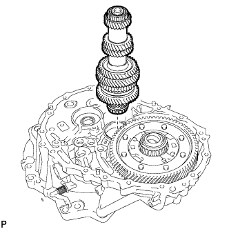
INSTALL INPUT SHAFT ASSEMBLY
-
Apply gear oil to all sliding and rotating parts.
-
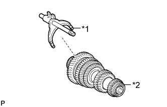
Text in Illustration *1 No. 1 Gear Shift Fork Shaft *2 Output Shaft Assembly Coat the No. 1 gear shift fork shaft with gear oil and install it to the output shaft assembly.
-
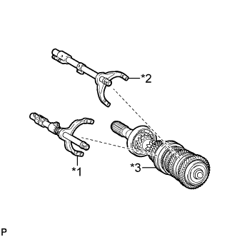
Text in Illustration *1 No. 2 Gear Shift Fork Shaft *2 No. 3 Gear Shift Fork Shaft *3 Input Shaft Assembly Coat the No. 2 gear shift fork shaft and the No. 3 gear shift fork shaft with gear oil and install them to the input shaft assembly.
-
Temporarily install the output shaft assembly to the input shaft assembly, and tie them with a rope or string.
-
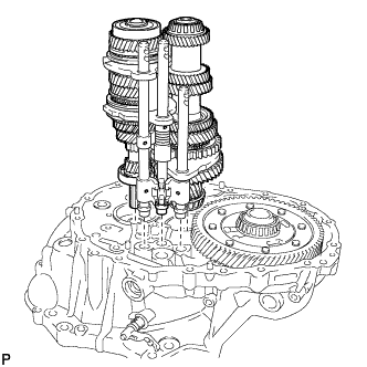
Install the input shaft assembly, output shaft assembly and 3 gear shift fork shaft assemblies to the front transaxle case.
-
-
INSTALL OUTER SELECT LEVER OIL SEAL
-
Text in Illustration *a Drive in Depth Using SST and a hammer, install a new outer select lever oil seal to the front transaxle case.
- SST
- 09950-60010 ( 09951-00240 )
- 09950-70010 ( 09951-07100 )
Standard depth 0.5 to 1.0 mm (0.0197 to 0.0393 in.) -
Coat the lip of the outer select lever oil seal with MP grease.
-
-
INSTALL OUTER SELECT LEVER
-
Clean and degrease the inner select lever set bolt and bolt hole.
-
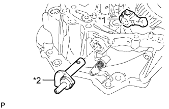
Text in Illustration *1 Inner Select Lever *2 Outer Select Lever Install the outer select lever and the inner select lever to the front transaxle case.
-
Coat the threads of the inner select lever set bolt with adhesive and install them using a 6 mm hexagon socket wrench.
Adhesive Toyota Genuine Adhesive 1324, Three Bond 1324 or equivalent - Torque:
- 28 N*m { 286 kgf*cm, 21 ft.*lbf }
-
-
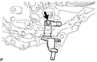
INSTALL SHIFT INTER LOCK PLATE
-
Install the shift inter lock plate to the front transaxle case.
-
-
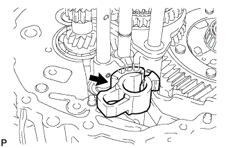
INSTALL SHIFT AND SELECT LEVER SHAFT ASSEMBLY
-
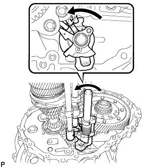
Turn the shift and select lever shaft assembly and the shift inter lock plate counterclockwise and install them to the front transaxle case.
Tech Tips
When installing the shift inter lock plate, make sure to engage it with the inner select lever.
-
-
INSTALL REVERSE SHIFT ARM BRACKET ASSEMBLY
-
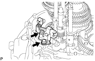
Install the reverse shift arm bracket assembly to the front transaxle case with the 2 bolts.
- Torque:
- 17 N*m { 173 kgf*cm, 13 ft.*lbf }
-
-
INSTALL REVERSE SHIFT FORK SHAFT ASSEMBLY
-
Text in Illustration *1 Reverse Shift Arm Bracket Assembly *2 Reverse Shift Fork Shaft Assembly Coat the reverse shift fork shaft assembly with gear oil and install it to the front transaxle case.
Tech Tips
When installing the reverse shift fork shaft assembly, make sure to engage it with the reverse shift arm bracket assembly.
-
-
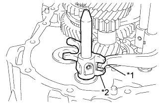
INSTALL REVERSE IDLER GEAR SUB-ASSEMBLY
-
Text in Illustration *1 Reverse Idler Gear Shaft *2 Reverse Idler Thrust Washer *3 Reverse Idler Gear Sub-assembly *a Center of Input Shaft *b Cutout Face of Reverse Idler Gear Shaft Coat the reverse idler gear sub-assembly, reverse idler thrust washer and the reverse idler gear shaft with gear oil, and install them as shown in the illustration.
Note
Aim the cutout face of the reverse idler gear shaft towards the center of the input shaft, and securely align the reverse idler gear shaft bolt installation surface with the bolt hole of the manual transmission case.
-
-
INSTALL MANUAL TRANSMISSION CASE
-
Clean and degrease the contact surfaces of the manual transmission case and the front transaxle case with non-residue solvent.
-
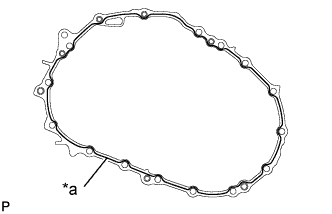
Text in Illustration *a Seal Packing
(Seal Diameter 1.2 mm (0.0472 in.))
Apply seal packing to the manual transmission case as shown in the illustration.
Seal packing Toyota Genuine Seal Packing 1281, Three Bond 1281 or equivalent Note
Assemble the parts within 10 minutes of application. Otherwise, the seal packing material must be removed and reapplied.
-
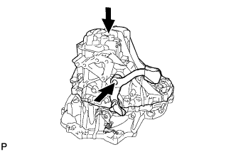
Push the outer No. 1 shift lever and install the manual transmission case to the front transaxle case.
Tech Tips
Pushing on the outer No. 1 shift lever allows the manual transmission case to be installed.
-
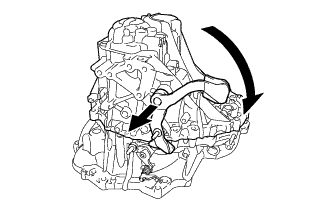
Pull the outer No. 1 shift lever out and turn it clockwise.
-
Install the 16 bolts to the manual transmission case.
- Torque:
- 29 N*m { 300 kgf*cm, 22 ft.*lbf }
-
-
INSTALL OUTER SHIFT LEVER E-RING
-
Install the outer shift lever E-ring to the outer No. 1 shift lever.
-
-
INSTALL TRANSMISSION CASE OIL SEAL
Text in Illustration *1 Installation depth
-
Coat the lip of a new oil seal with MP grease.
-
Using SST and a hammer, install the transmission case oil seal.
- SST
- 09316-60011 ( 09316-00011 )
Installation depth 10.6 to 11.6 mm (0.417 to 0.457 in.) Note
Do not damage the oil seal lip.
-
-
INSTALL TRANSAXLE CASE OIL SEAL
Text in Illustration *1 Installation depth
-
Coat the lip of a new oil seal with MP grease.
-
Using SST and a hammer, install the transaxle case oil seal.
- SST
- 09630-24014 ( 09620-24051 )
- 09950-60010 ( 09951-00410, 09951-00520, 09952-06010 )
- 09950-70010 ( 09951-07100 )
Installation depth 1.4 to 2.4 mm (0.055 to 0.094 in.) Note
Do not damage the oil seal lip.
-
-
INSTALL SHIFT DETENT BALL
-
Clean and degrease the 2 shift detent ball plugs and plug holes.
-
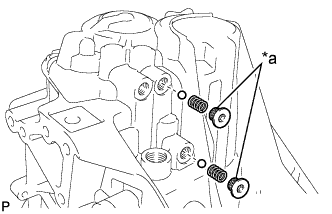
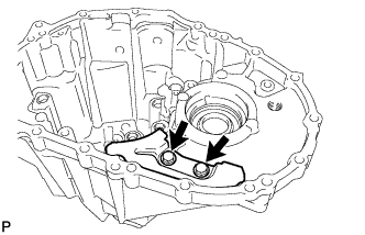
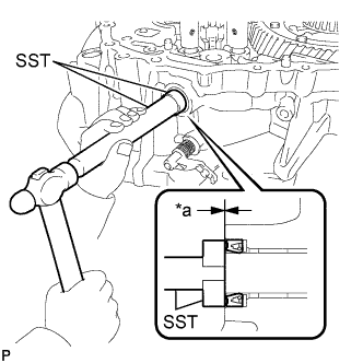
Text in Illustration *a Adhesive Install the 2 shift detent balls and the 2 compression springs to the manual transmission case.
-
Coat the threads of the 2 shift detent ball plugs with adhesive and install them using a 6 mm hexagon socket wrench.
Adhesive Toyota Genuine Adhesive 1344, Three Bond 1344 or equivalent - Torque:
- 22 N*m { 224 kgf*cm, 16 ft.*lbf }
-
Clean and degrease the shift detent ball plug and plug hole.
-
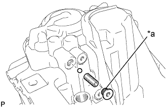
Text in Illustration *a Adhesive Install the shift detent ball and the compression spring to the manual transmission case.
-
Coat the threads of the shift detent ball plug with adhesive and install it using a 6 mm hexagon socket wrench.
Adhesive Toyota Genuine Adhesive 1344, Three Bond 1344 or equivalent - Torque:
- 22 N*m { 224 kgf*cm, 16 ft.*lbf }
-
-
INSTALL LOCK BALL PIN
-
Clean and degrease the shift detent ball plug and plug hole.
-
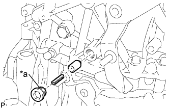
Text in Illustration *a Adhesive Install the lock ball pin and the compression spring to the manual transmission case.
-
Coat the threads of the shift detent ball plug with adhesive and install it using a 10 mm hexagon socket wrench.
Adhesive Toyota Genuine Adhesive 1344, Three Bond 1344 or equivalent - Torque:
- 25 N*m { 250 kgf*cm, 18 ft.*lbf }
-
-
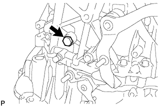
INSTALL REVERSE IDLER GEAR SHAFT BOLT
-
Clean and degrease the reverse idler gear shaft bolt.
-
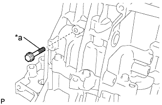
Text in Illustration *a Adhesive Coat the reverse idler gear shaft bolt with adhesive and install it to the manual transmission case with a new gasket.
Adhesive Toyota Genuine Adhesive 1324, Three Bond 1324 or equivalent - Torque:
- 30 N*m { 306 kgf*cm, 22 ft.*lbf }
-
-
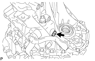
INSTALL NO. 1 LOCK BALL ASSEMBLY
-
Clean and degrease the threads of the No. 1 lock ball assembly and bolt hole.
-
Coat the threads of the No. 1 lock ball assembly with adhesive and install it to the manual transmission case.
Adhesive Toyota Genuine Adhesive 1344, Three Bond 1344 or equivalent - Torque:
- 29 N*m { 300 kgf*cm, 22 ft.*lbf }
-
-
INSTALL TRANSMISSION CASE PLUG
-
Install the transmission case plug to the manual transmission case with a new gasket.
- Torque:
- 28 N*m { 286 kgf*cm, 21 ft.*lbf }
-
Install the transmission case plug to the manual transmission case with a new gasket.
- Torque:
- 40 N*m { 410 kgf*cm, 30 ft.*lbf }
-
-
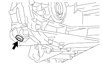
INSTALL NO. 1 TRANSMISSION CASE PLUG
-
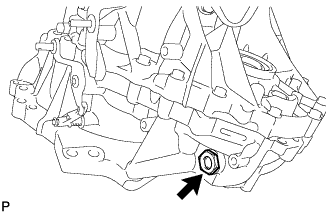
Using a 30 mm socket wrench, install the No. 1 transmission case plug to the front transaxle case with a new gasket.
- Torque:
- 65 N*m { 663 kgf*cm, 48 ft.*lbf }
-
-
INSTALL CLUTCH RELEASE WITH BEARING CYLINDER ASSEMBLY
-
Clean and degrease all installation surfaces for the clutch release with bearing cylinder assembly.
-
Temporarily tighten the bleeder clutch release tube onto the clutch release with bearing cylinder assembly.
-
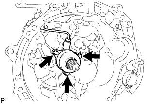
Install the new clutch release with the bearing cylinder assembly with 3 new bolts.
Note
-
The clutch release with bearing cylinder assembly and installation bolts cannot be reused and must be replaced with new ones.
-
Clean and degrease all installation surfaces and make sure the clutch release with bearing cylinder assembly fits securely with the transaxle during installation. The first bolt should be tightened by hand the clutch release with bearing cylinder assembly.
-
Ensure that none of the clutch disc spline grease adheres to the clutch release with bearing cylinder assembly.
-
The clutch release with bearing cylinder assembly cannot be disassembled.
- Torque:
- 23 N*m { 229 kgf*cm, 17 ft.*lbf }
-
-
Install the clutch tube boot onto the transaxle.
-
Install the release cylinder bleeder plug onto the clutch release bleeder.
- Torque:
- 8.4 N*m { 86 kgf*cm, 74 in.*lbf }
-
Install the release cylinder bleeder plug cap.
-
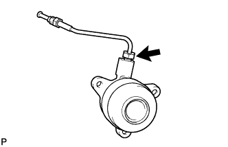
Text in Illustration *1 Bleeder clutch release tube *2 Clutch release bleeder Temporarily tighten the bleeder clutch release tube onto the clutch release bleeder.
-
Temporarily tighten the 2 bolts and install the clutch release bleeder.
-
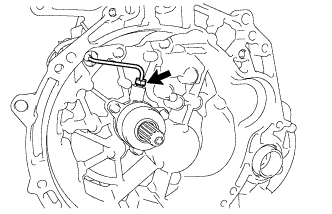
Using a union nut wrench 10 mm, install the bleeder clutch release tube onto the clutch release with bearing cylinder assembly.
- Torque:
- 15 N*m { 155 kgf*cm, 11 ft.*lbf }
Note
Use the formula to calculate special torque values for situations when union nut wrench is combined with a torque wrench Click here.
-
-
REMOVE CLUTCH RELEASE BLEEDER SUB-ASSEMBLY
-
Separate the bleeder clutch release tube from the clutch release bleeder.
-
Remove the 2 bolts and the clutch release bleeder.
-
-
INSPECT CLUTCH PIPE LINE
-
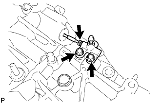
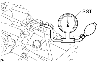
Using SST, apply pressure of 0.1 MPa to the clutch pipe location shown in the illustration and confirm that pressure is maintained for 15 seconds or more.
- SST
- 09992-00242
If the pressure drops, replace the bleeder clutch release tube.
-
-
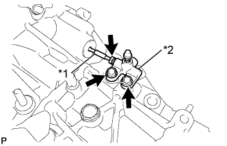
INSTALL CLUTCH RELEASE BLEEDER SUB-ASSEMBLY
Text in Illustration *1 Bleeder clutch release tube *2 Clutch release bleeder
-
Temporarily tighten the bleeder clutch release tube onto the clutch release bleeder.
-
Install the 2 bolts and clutch release bleeder.
- Torque:
- 17 N*m { 170 kgf*cm, 12 ft.*lbf }
-
Using a union nut wrench 10 mm, install the bleeder clutch release tube.
- Torque:
- 15 N*m { 155 kgf*cm, 11 ft.*lbf }
Note
Use the formula to calculate special torque values for situations when union nut wrench is combined with a torque wrench Click here.
-
-
INSTALL NO. 1 CLUTCH HOUSING COVER
-
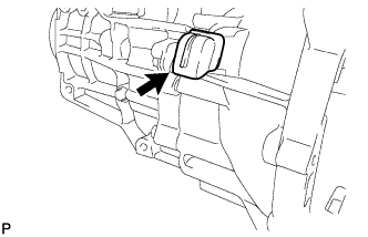
Install the No. 1 clutch housing cover onto the transaxle.
-
-
INSTALL WIRE HARNESS CLAMP BRACKET
-
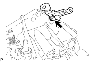
Install the wire harness clamp bracket to the front transaxle case with the bolt.
- Torque:
- 13 N*m { 130 kgf*cm, 9 ft.*lbf }
-
Install the wire harness clamp bracket to the manual transmission case with the bolt.
- Torque:
- 13 N*m { 130 kgf*cm, 9 ft.*lbf }
-
-
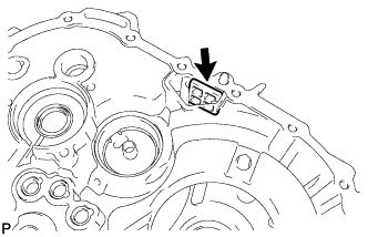
INSTALL BACK-UP LIGHT SWITCH ASSEMBLY
-
Using SST, install the back-up light switch assembly and a new gasket to the manual transmission case.
- SST
- 09817-16011
- Torque:
- 40 N*m { 410 kgf*cm, 30 ft.*lbf }
-
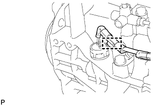
Engage the wire harness clamp of the back-up light switch assembly to the wire harness clamp bracket.
-
-
INSTALL MANUAL TRANSMISSION DRAIN PLUG
-
Using a 10 mm hexagon socket wrench, install the manual transmission drain plug to the front transaxle case with a new gasket.
- Torque:
- 45 N*m { 459 kgf*cm, 33 ft.*lbf }
-
-
INSTALL MANUAL TRANSMISSION FILLER PLUG
-
Install the manual transmission filler plug to the manual transmission case with a new gasket.
- Torque:
- 39 N*m { 400 kgf*cm, 29 ft.*lbf }
-