СТАРТЕР (для моделей мощностью 0,8 кВт) ПРОВЕРКА
-
INSPECT STARTER ASSEMBLY
Note
The following tests must be performed within 5 seconds to prevent the coil from burning out.
-
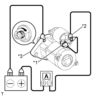
Perform a pull-in test.
-
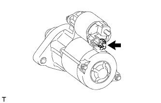
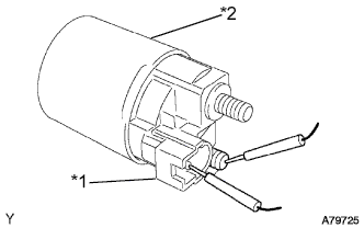
Remove the nut and disconnect the motor lead wire from terminal C.
-
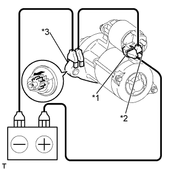
Text in Illustration *1 Terminal 50 *2 Terminal C *3 Body Connect the battery to the magnet starter switch as shown in the illustration. Check that the clutch pinion gear is extended.
If the clutch pinion gear does not move, replace the magnet starter switch assembly.
-
-
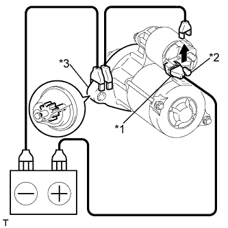
Text in Illustration *1 Terminal 50 *2 Terminal C *3 Body Perform a holding test.
-
Disconnect the negative (-) lead from terminal C. Check that the clutch pinion gear remains extended.
If the clutch pinion gear returns inward, replace the magnet starter switch assembly.
-
-
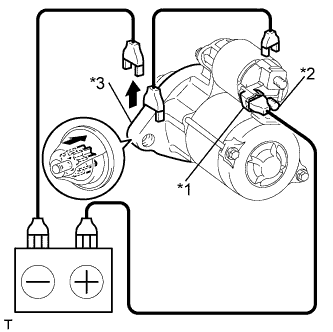
Text in Illustration *1 Terminal 50 *2 Terminal C *3 Body Inspect the clutch pinion gear return.
-
Disconnect the negative (-) lead from the starter body. Check that the clutch pinion gear returns.
If the clutch pinion gear does not return inward, replace the magnet starter switch assembly.
-
-
Perform a no-load performance test.
-
Connect the motor lead wire to terminal C. Make sure that the lead is not grounded.
- Torque:
- 9.8 N*m { 100 kgf*cm, 87 in.*lbf }
-
Clamp the starter in a vise.
Note
Do not clamp the vise too tightly.
-
Text in Illustration *1 Terminal 50 *2 Terminal 30 *3 Body Connect the battery and an ammeter to the starter as shown in the illustration.
-
Check that the starter rotates smoothly and steadily with the clutch pinion gear extended.
Measure the current according to the value(s) in the table below.
Standard Current Tester Connection Condition Specified Condition Battery positive terminal - Terminal 30 - Terminal 50 11.5 V Below 90 A If the result is not as specified, replace the starter assembly.
-
-
-
INSPECT STARTER ARMATURE ASSEMBLY
-
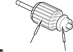
Check the commutator.
-
Measure the resistance according to the value(s) in the table below.
Standard Resistance Tester Connection Condition Specified Condition Segment - Segment Always Below 1 Ω If the result is not as specified, replace the starter armature assembly.
-
-
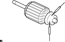
Check the commutator.
-
Measure the resistance according to the value(s) in the table below.
Standard Resistance Tester Connection Condition Specified Condition Commutator - Armature core Always 10 MΩ or higher If the result is not as specified, replace the starter armature assembly.
-
-
Check the commutator surface for dirt and burns.
If the surface is dirty or burnt, restore it with sandpaper (No. 400) or a lathe.
-
Check the commutator for circle runout.
-
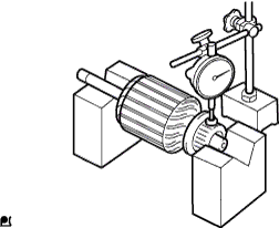
Place the commutator on V-blocks.
-
Using a dial indicator, measure the circle runout.
Maximum runout 0.05 mm (0.00197 in.) If the runout is greater than the maximum, replace the starter armature assembly.
-
-
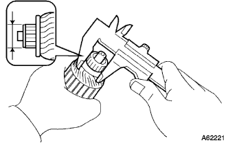
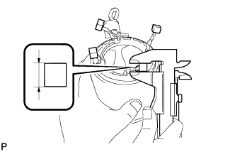
Using a vernier caliper, measure the commutator diameter.
Standard diameter 28.0 mm (1.10 in.) Minimum diameter 27.0 mm (1.06 in.) If the diameter is less than the minimum, replace the starter armature assembly.
-
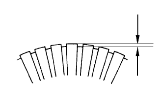
Check that the undercut portion between the segments is free of foreign matter and measure its depth.
Standard undercut depth 0.6 mm (0.0236 in.) Minimum undercut depth 0.2 mm (0.00787 in.) If the undercut depth is less than the minimum, adjust it with a hacksaw blade.
-
-
INSPECT FIELD COIL
-
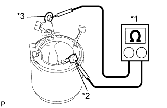
Text in Illustration *1 Ohmmeter *2 Brush Lead *3 Terminal C Measure the resistance according to the value(s) in the table below.
Standard Resistance Tester Connection Condition Specified Condition Terminal C - Brush lead Always Below 1 Ω If the result is not as specified, replace the starter yoke assembly.
-
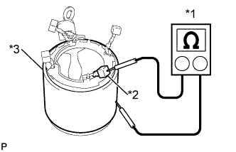
Text in Illustration *1 Ohmmeter *2 Brush Lead *3 Body Measure the resistance according to the value(s) in the table below.
Standard Resistance Tester Connection Condition Specified Condition Brush lead - Body Always 10 MΩ or higher If the result is not as specified, replace the starter yoke assembly.
-
-
INSPECT STARTER BRUSH
-
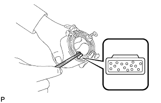
Using a vernier caliper, measure the brush length.
Standard length 10.0 mm (0.394 in.) Minimum length 6.0 mm (0.236 in.) If the length is less than the minimum, replace the starter brush.
-
-
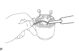
REPLACE STARTER BRUSH
-
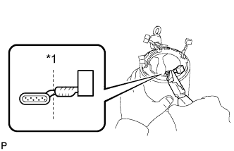
Text in Illustration *1 Cut Cut the brush lead wire on the terminal side.
-
Smooth the brush lead wire using a file.
Note
Only a small area can be filed, do not damage the yoke.
-
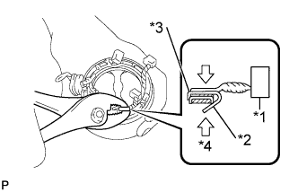
Text in Illustration *1 Brush *2 Plate *3 Weld Side *4 Press Using pliers, pinch the plate of the brush (service part) on the weld side of the terminal lead wire and apply force.
-
Apply solder to the contact surface.
Tech Tips
-
Heat the contact surface well. Apply a sufficient amount of solder to the inside of the plate while paying attention not to apply it to the lead wire.
-
Do not apply solder to the field coil.
-
-
-
INSPECT STARTER BRUSH SPRING
-
Check visually.
Specified Condition No rust, abrasion or damage. -
Using a vernier caliper, measure the brush spring length.
Standard length 21.5 mm (0.846 in.)
-
-
INSPECT STARTER CLUTCH SUB-ASSEMBLY
-
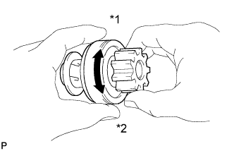
Text in Illustration *1 Free *2 Look Hold the starter clutch, rotate the pinion gear clockwise, and check that it turns freely. Try to rotate the pinion gear counterclockwise and check that it locks.
If necessary, replace the starter clutch sub-assembly.
-
-
INSPECT MAGNET STARTER SWITCH ASSEMBLY
-
Check the plunger.
-
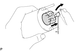
Text in Illustration *1 Plunger Push in the plunger and check that it returns quickly to its original position.
If necessary, replace the magnet starter switch assembly.
-
-
Check the pull-in coil for an open circuit.
-
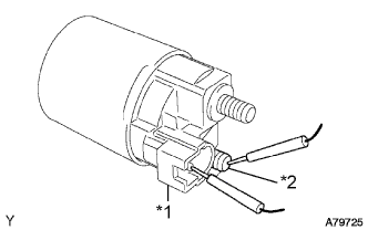
Text in Illustration *1 Terminal 50 *2 Terminal C Measure the resistance according to the value(s) in the table below.
Standard Resistance Tester Connection Condition Specified Condition Terminal 50 - Terminal C Always Below 1 Ω If the result is not as specified, replace the magnet starter switch assembly.
-
-
Check the hold-in coil for an open circuit.
-
Text in Illustration *1 Terminal 50 *2 Body Measure the resistance according to the value(s) in the table below.
Standard Resistance Tester Connection Condition Specified Condition Terminal 50 - Body Always Below 2 Ω If the result is not as specified, replace the magnet starter switch assembly.
-
-