СТАРТЕР (для моделей мощностью 0,8 кВт) ПОВТОРНАЯ СБОРКА

-
INSTALL DUST STARTER PROTECTOR
-
Install the dust starter protector to the starter commutator end frame.
-
-
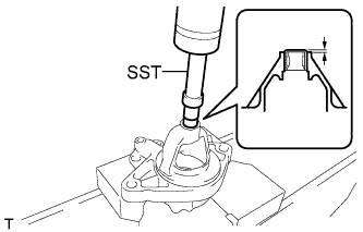
INSTALL STARTER HOUSING BEARING
-
Using SST and a press, insert a new bearing into the drive housing.
- SST
- 09820-36010
Standard length 0.5 to 1.5 mm (from the end of the housing)
-
-
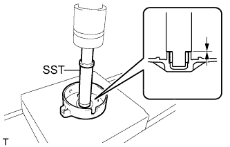
INSTALL BEARING
-
Using SST and a press, insert a new bearing into the end of the commutator end frame.
- SST
- 09221-25026 ( 09221-00160 )
Standard length 0 mm (from the end of the frame) -
Install the clutch and pinion stop nut (inner) onto the armature.
-
-
INSTALL STARTER CLUTCH SUB-ASSEMBLY
-
Apply high temperature grease to the clutch bushing, spline and pinion stop nut (inner).
-
Install the clutch and pinion stop nut (inner) onto the armature.
-
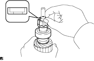
Apply high temperature grease onto the new snap ring and install it onto the armature groove.
-
Compress the snap ring using a vise.
-
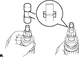
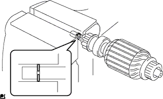
While holding the clutch by hand, slightly tap the armature shaft tip with a plastic faced hammer until the pinion stop nut (inner) fits over the snap ring.
-
Install the pinion stop nut (outer).
-
-
INSTALL STARTER ARMATURE ASSEMBLY
-
Clamp the armature shaft in a visa.
Note
Do not clamp the vise too tightly.
-
Install the armature onto the starter yoke.
-
-
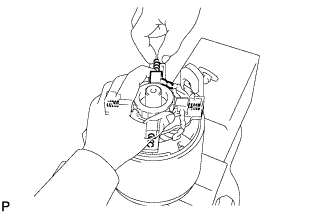
INSTALL STARTER BRUSH SPRING
-
Install the 4 starter brush springs and the starter brush holder.
Note
Do not allow the brush springs to fly off.
-
-
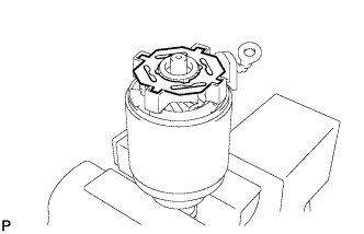
INSTALL STARTER PLATE
-
Install the starter plate.
-
-
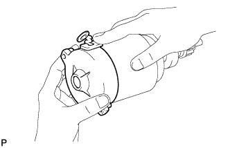
INSTALL STARTER COMMUTATOR END FRAME ASSEMBLY
-
Install the starter commutator end frame.
-
-
INSTALL STARTER YOKE ASSEMBLY
-
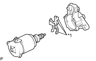
Text in Illustration *1 High Temperature Grease Apply high temperature grease to the contact surfaces between the pinion drive lever and the housing, clutch, and plunger.
-
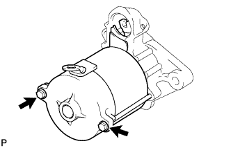
Install the yoke and pinion drive lever onto the housing with the 2 through bolts.
- Torque:
- 5.9 N*m { 60 kgf*cm, 52 in.*lbf }
-
-
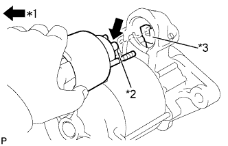
INSTALL MAGNET STARTER SWITCH ASSEMBLY
-
Apply high temperature grease onto the magnet starter switch plunger.
Text in Illustration *1 Apply High Temperature Grease *2 Plunger Hook *3 Pinion Drive Lever -
Place the plunger hook in place on the pinion drive lever, and then install the magnet starter switch.
-
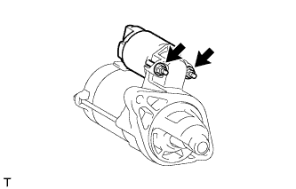
Install the 2 nuts.
- Torque:
- 8.3 N*m { 85 kgf*cm, 73 in.*lbf }
-
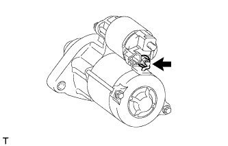
Install the lead wire onto the magnet switch terminal with the nut.
- Torque:
- 9.8 N*m { 100 kgf*cm, 87 in.*lbf }
-