ВЫПУСКНОЙ КОЛЛЕКТОР УСТАНОВКА

-
INSTALL NO. 1 MANIFOLD CONVERTER INSULATOR
-
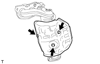
Install the No. 1 manifold converter insulator with the 3 bolts.
- Torque:
- 8.5 N*m { 87 kgf*cm, 75 in.*lbf }
-
-
INSTALL EXHAUST MANIFOLD
-
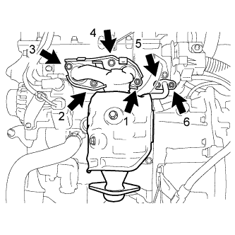
Place the 2 new gaskets and install the exhaust manifold, tightening the nuts and bolts in the sequence shown in the illustration.
- Torque:
- 28 N*m { 286 kgf*cm, 21 ft.*lbf }
-
-
INSTALL NO. 1 EXHAUST MANIFOLD HEAT INSULATOR
-
Install the No. 1 exhaust manifold heat insulator, tightening the nuts and bolts in the sequence shown in the illustration.
- Torque:
- 8.5 N*m { 87 kgf*cm, 75 in.*lbf }
-
-
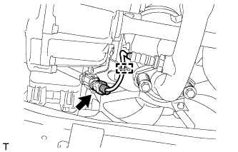
INSTALL AIR FUEL RATIO SENSOR
-
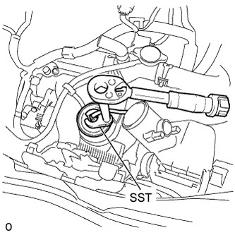
Using SST, install the air fuel ratio sensor to the exhaust manifold.
- SST
- 09224-00010
- Torque:
- without SST
- 44 N*m { 449 kgf*cm, 32 ft.*lbf }
- with SST
- 40 N*m { 408 kgf*cm, 30 ft.*lbf }
Note
-
The "with SST" torque value is effective when using SST with a fulcrum length of 30 mm (1.18 in.).
-
The "with SST" torque value is effective when using a torque wrench with a fulcrum length of 300 mm (11.81 in.) Click here.
-
This torque value is effective when SST is parallel to the torque wrench.
-
Install the wire harness clamp and connect the air fuel ratio sensor connector.
-
-
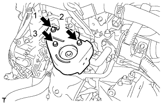
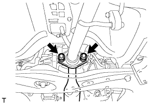
INSTALL MANIFOLD STAY
-
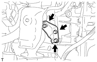
After temporarily tightening the manifold stay until the nut is firm against the exhaust manifold, fully tighten the manifold stay to the block with the 2 bolts and then fully tighten the nut on the exhaust manifold side.
- Torque:
- 24 N*m { 245 kgf*cm, 18 ft.*lbf }
-
-
INSTALL FRONT EXHAUST PIPE ASSEMBLY
-
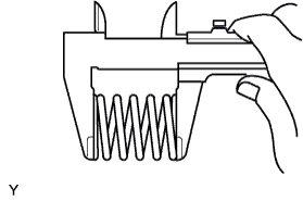
Using a vernier caliper, measure the free length of the compression springs.
Minimum Length Item Length Front 41.5 mm (1.634 in.) Tech Tips
If the length is not as specified, replace the compression spring.
-
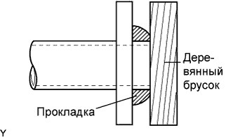
Using a plastic hammer and a wooden block, tap in a new exhaust pipe gasket until its surface is flush with the exhaust manifold.
Note
-
Install the gasket in the correct direction.
-
Do not reuse the gasket.
-
Do not damage the gasket by dropping it, etc.
-
Do not damage the outer surface of the gasket.
-
Do not push in the gasket with the exhaust pipe when connecting it.
-
After the installation, check that the gaps between the flanges of the exhaust manifold and front exhaust pipe assembly are consistent front-to-rear and left-to-right.
-
-
Install the front exhaust pipe assembly to the exhaust manifold with the 2 bolts and the 2 compression springs.
- Torque:
- 43 N*m { 438 kgf*cm, 32 ft.*lbf }
-
Using a vernier caliper, measure the free length of the compression springs.
Minimum Length Item Length Rear 38.5 mm (1.594 in.) Tech Tips
If the length is not as specified, replace the compression spring.
-
Using a plastic hammer and a wooden block, tap in a new exhaust pipe gasket until its surface is flush with the exhaust manifold.
Note
-
Install the gasket in the correct direction.
-
Do not reuse the gasket.
-
Do not damage the gasket by dropping it, etc.
-
Do not damage the outer surface of the gasket.
-
Do not push in the gasket with the exhaust pipe when connecting it.
-
After the installation, check that the gaps between the flanges of the front exhaust pipe assembly and tail exhaust pipe assembly are consistent front-to-rear and left-to-right.
-
-
Install the front exhaust pipe assembly to the tail exhaust pipe assembly with the 2 bolts and the 2 compression springs.
- Torque:
- 43 N*m { 438 kgf*cm, 32 ft.*lbf }
-
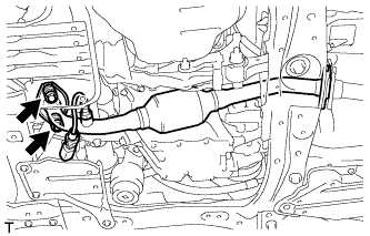
Connect the oxygen sensor connector and engage the clamp.
-
-
INSTALL AIR CLEANER AND HOSE
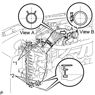
Text in Illustration *1 Clamp *2 Guide
-
Align the 2 hinges with the case guide, to insert the case into the groove, and engage the 2 clamps to install the air cleaner cap.
-
Connect the air cleaner hose with the hose clamp.
- Torque:
- 3.0 N*m { 31 kgf*cm, 27 in.*lbf }
Tech Tips
Install the clip as shown in the illustration.
-
Connect the ventilation hose with the clip
Tech Tips
Install the clip as shown in the illustration.
-
-
INSPECT FOR EXHAUST GAS LEAK