НАГНЕТАЮЩИЙ ТОПЛИВНЫЙ НАСОС УСТАНОВКА
-
INSTALL SUPPLY PUMP DRIVE COUPLING
-
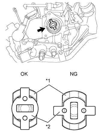
Text in Illustration *1 Camshaft *2 Supply Pump Drive Coupling Install the supply pump drive coupling into the camshaft.
Note
Install the supply pump drive coupling in the correct direction.
-
-
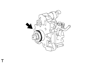
INSTALL SUPPLY PUMP ASSEMBLY
Note
When installing, clean the seal surfaces of the fuel inlet pipe, supply pump and common rail.
-
Apply a light coat of engine oil to a new O-ring.
-
Install the O-ring onto the supply pump.
-
Temporarily install the supply pump with the 3 bolts.
-
Remove the plastic bag and rubber band from the supply pump.
-
-
INSTALL FUEL INLET PIPE SUB-ASSEMBLY
Note
-
When replacing the supply pump, the fuel inlet pipe must also be replaced.
-
Replace the fuel inlet pipe with a new one when the fuel inlet pipe has been removed and reinstalled more than 5 times.
-
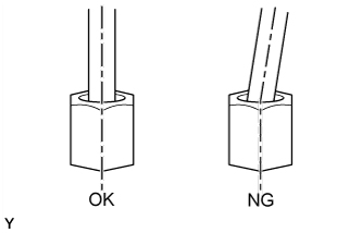
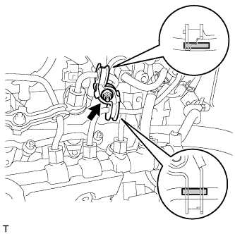
Temporarily install the fuel inlet pipe onto the supply pump and common rail.
Note
Install the pipe and union nut vertically, not at a tilt.
-
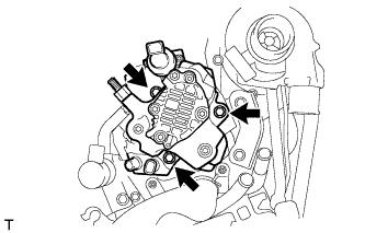
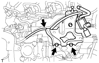
Tighten the supply pump with the 3 bolts.
- Torque:
- 21 N*m { 214 kgf*cm, 15 ft.*lbf }
-
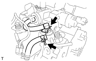
Using a union nut wrench (17 mm), tighten the fuel inlet pipe union nut on the common rail side.
- Torque:
- 28 N*m { 286 kgf*cm, 20 ft.*lbf }
Note
Use the formula to calculate special torque values for situations where a union nut wrench is combined with a torque wrench Click here.
-
Using a wrench (17 mm), hold the supply pump nut, using a union nut wrench (17 mm), tighten the fuel inlet pipe union nut on the supply pump side.
- Torque:
- 28 N*m { 286 kgf*cm, 20 ft.*lbf }
Note
Use the formula to calculate special torque values for situations where a union nut wrench is combined with a torque wrench Click here.
-
Connect the No. 2 fuel hose.
-
Connect the nozzle leakage pipe and install a new retainer spring onto the supply pump.
-
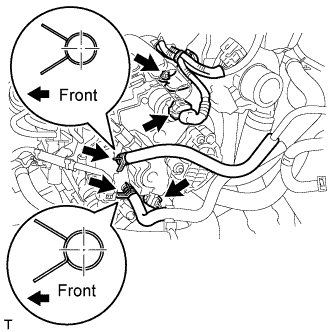
Connect the 2 connectors.
-
Connect the harness bracket with bolt.
- Torque:
- 8.0 N*m { 82 kgf*cm, 71 in.*lbf }
-
Connect the 2 fuel hoses.
-
-
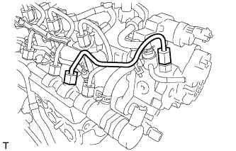
INSTALL NO. 2 INJECTION PIPE CLAMP
-
Install both sides of the No. 2 injection pipe clamp with the nut as shown in the illustration.
- Torque:
- 9.0 N*m { 92 kgf*cm, 80 in.*lbf }
-
-
INSTALL NO. 1 EGR COOLER BRACKET
-
Install the No. 1 EGR cooler bracket with the 2 bolts.
- Torque:
- 23 N*m { 235 kgf*cm, 17 ft.*lbf }
-
Connect the vacuum hose.
-
-
INSTALL EGR WITH COOLER PIPE ASSEMBLY
-
Install the EGR with cooler pipe assembly Click here.
-
-
BLEED AIR FROM FUEL SYSTEM
-
INSPECT FOR FUEL LEAK
-
Подсоедините портативный диагностический прибор к разъему DLC3.
-
Установите замок зажигания в положение ON (ВКЛ).
-
Включите портативный диагностический прибор.
-
Войдите в следующие меню: Powertrain / Engine / Active Test.
-
Выполните диагностику в режиме Active Test.
Дисплей портативного диагностического прибора Описание проверки Диапазон регулирования Примечания по диагностике Test the Fuel Leak Нагнетание давления в топливной системе Common Rail и проверка утечек Stop/Start (остановить/запустить) Выполните проверку топливной системы высокого давления.
Испытание возможно при соблюдении следующих условий:
-
Прогрейте двигатель.
-
Автомобиль остановлен.
-
Напряжение аккумуляторной батареи не менее 12 В.
-
Регенерация в отношении твердых частиц не производится.
-
Частота вращения коленчатого вала двигателя – ниже 4000 об/мин.
Результат проверки действительного автомобиля:
-
Частота вращения коленчатого вала двигателя: 2702 об/мин
-
Давление в топливной системе: 108570 кПа
-
Заданное давление в топливной системе Common Rail 105500 кПа
-
Заданный ток накачки SCV: 1,2 A
-
MAP: 127 кПа
-
MAF: 28 г/с
-
-