БЛОК ДВИГАТЕЛЯ УСТАНОВКА
-
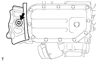
INSTALL OIL PAN COVER
-
Install the oil pan cover with the bolt and washer plate.
- Torque:
- 7.0 N*m { 71 kgf*cm, 62 in.*lbf }
-
-
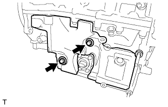
INSTALL NO. 2 OIL PAN COVER SILENCER
-
Install the No. 2 oil pan cover silencer with the 2 washer plates and 2 bolts.
- Torque:
- 7.0 N*m { 71 kgf*cm, 62 in.*lbf }
-
-
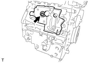
INSTALL CYLINDER BLOCK SIDE COVER
-
Install the cylinder block side cover with the bolt and washer plate.
- Torque:
- 37 N*m { 377 kgf*cm, 27 ft.*lbf }
-
-
INSTALL HARNESS BRACKET (w/o Air Conditioning System)
-
Install the harness bracket with the bolt.
- Torque:
- 13 N*m { 130 kgf*cm, 9 ft.*lbf }
-
-
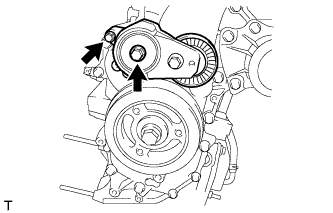
INSTALL V-RIBBED BELT TENSIONER ASSEMBLY
-
Install the V-ribbed belt tensioner with the 2 bolts.
- Torque:
- 24 N*m { 245 kgf*cm, 18 ft.*lbf }
-
-
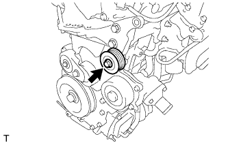
INSTALL IDLER PULLEY SUB-ASSEMBLY
-
Install the idler pulley with the bolt.
- Torque:
- 40 N*m { 408 kgf*cm, 30 ft.*lbf }
-
-
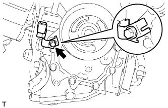
INSTALL CAMSHAFT POSITION SENSOR
-
Install the camshaft position sensor with the bolt.
- Torque:
- 7.0 N*m { 71 kgf*cm, 62 in.*lbf }
-
Install the harness bracket with the bolt.
- Torque:
- 11 N*m { 112 kgf*cm, 8 ft.*lbf }
-
-
INSTALL VACUUM PUMP ASSEMBLY
-
Install 2 new O-rings to the vacuum pump.
-
Install the vacuum pump with the 2 bolts.
- Torque:
- 21 N*m { 214 kgf*cm, 15 ft.*lbf }
-
-
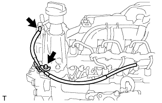
INSTALL OIL LEVEL DIPSTICK GUIDE
-
Install a new O-ring to the oil level dipstick guide.
-
Install the oil level dipstick guide with the 2 bolts.
- Torque:
- 9.0 N*m { 92 kgf*cm, 80 in.*lbf }
-
-
INSTALL ENGINE OIL LEVEL DIPSTICK
-
INSTALL WATER INLET PIPE
-
Install the water inlet pipe with the 2 bolts.
- Torque:
- 9.0 N*m { 92 kgf*cm, 80 in.*lbf }
-
-
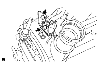
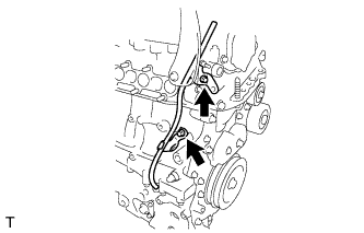
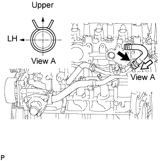
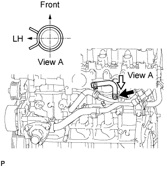
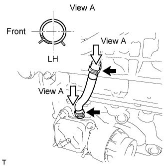
INSTALL WATER INLET HOSE LH
-
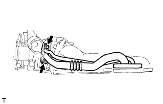
Install the water inlet hose LH.
Tech Tips
The clip at the water inlet housing can be installed in any orientation, as long as it does not contact any of the surrounding parts.
-
-
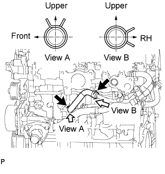
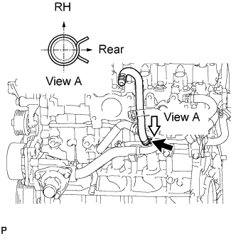
INSTALL WATER INLET HOSE RH
-
Install the water inlet hose RH.
-
-
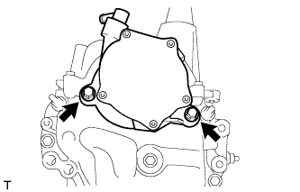
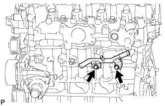
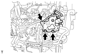
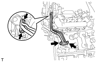
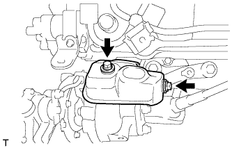
INSTALL WATER BY-PASS PIPE SUB-ASSEMBLY
-
Install a new O-ring to the water by-pass pipe.
Note
Apply water to all around the O-ring's inserting hole surface of the water inlet housing before installing the water by-pass pipe sub-assembly.
-
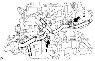
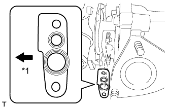
Install the water by-pass pipe with the 2 bolts, as shown in the illustration.
- Torque:
- 9.0 N*m { 92 kgf*cm, 80 in.*lbf }
-
-
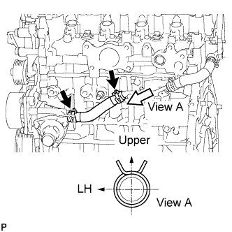
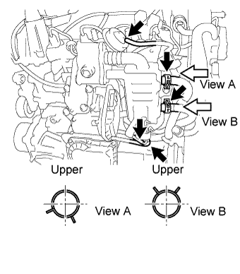
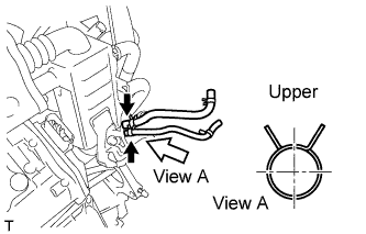
INSTALL WATER BY-PASS HOSE
-
Install the water by-pass hose.
-
-
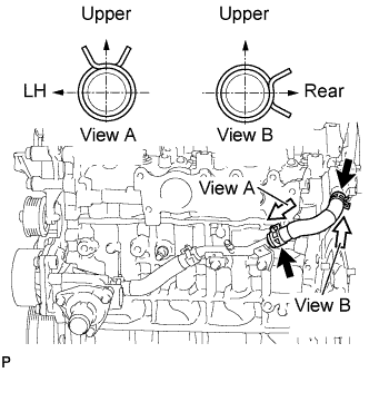
INSTALL NO. 2 WATER BY-PASS HOSE
-
Install the No. 2 water by-pass hose.
-
-
INSTALL NO. 3 WATER BY-PASS HOSE
-
Install the No. 3 water by-pass hose.
-
-
INSTALL NO. 4 WATER BY-PASS HOSE
-
Install the No. 4 water by-pass hose.
-
-
INSTALL OIL COOLER HOSE SUB-ASSEMBLY
-
Install the oil cooler hose.
-
-
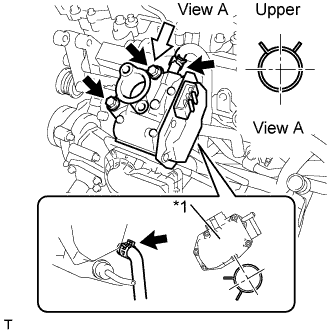
INSTALL NO. 2 OIL COOLER HOSE
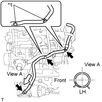
Text in Illustration *1 Paint Mark
-
Install the No. 2 oil cooler hose.
Note
Align the oil cooler hose paint mark with the clamp center.
-
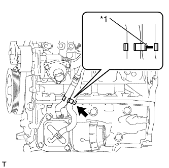
Text in Illustration *1 Paint Mark Install the hose clamp.
Note
Align the oil cooler hose paint mark with the clamp center.
-
-
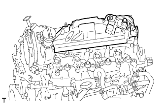
INSTALL NO. 2 CYLINDER HEAD COVER
-
Install the No. 2 cylinder head cover.
-
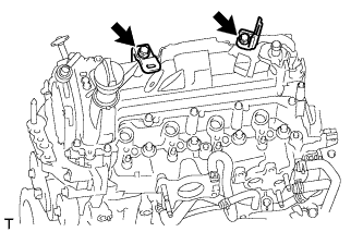
Install the 2 harness brackets with the 2 bolts.
- Torque:
- 11 N*m { 112 kgf*cm, 8 ft.*lbf }
-
-
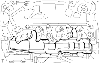
INSTALL NO. 1 INTAKE MANIFOLD INSULATOR
-
Install the No. 1 intake manifold insulator.
-
-
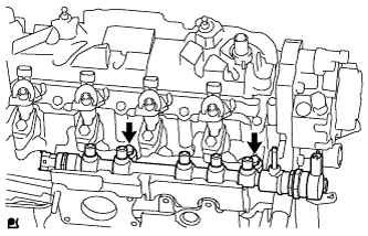
INSTALL COMMON RAIL ASSEMBLY
-
Install the common rail with 2 bolts.
- Torque:
- 21 N*m { 214 kgf*cm, 15 ft.*lbf }
-
-
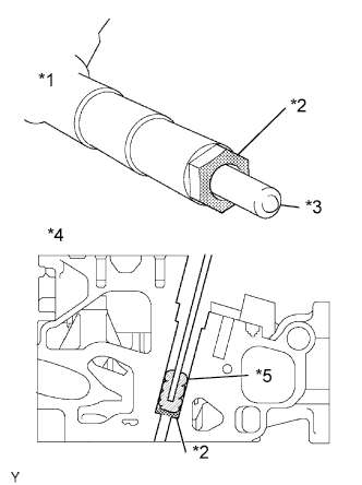
INSTALL SUPPLY PUMP DRIVE COUPLING
-
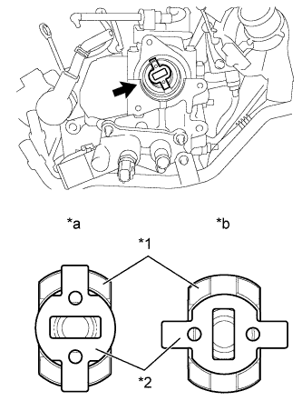
Text in Illustration *1 Camshaft *2 Supply Pump Drive Coupling *a Correct *b Incorrect Install the supply pump drive coupling into the camshaft.
Note
Install the supply pump drive coupling in the correct direction.
-
-
TEMPORARILY TIGHTEN SUPPLY PUMP ASSEMBLY
Note
When installing, clean the seal surfaces of the fuel inlet pipe, supply pump and common rail.
-
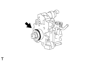
Apply a light coat of engine oil to a new O-ring.
-
Install the O-ring onto the supply pump.
-
Temporarily tighten the supply pump with the 3 bolts.
-
-
INSTALL FUEL INLET PIPE SUB-ASSEMBLY
Note
-
When replacing the supply pump. the fuel inlet pipe must also be replaced.
-
Replace the fuel inlet pipe with a new one when the fuel inlet pipe has been removed and reinstalled more than 5 times.
-
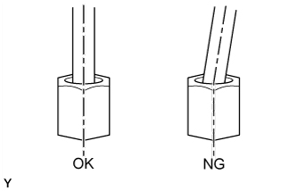
Temporarily tighten the fuel inlet pipe onto the supply pump and common rail.
Note
Install the pipe and union nut vertically. not at a tilt.
-
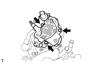
Fully tighten the supply pump with the 3 bolts.
- Torque:
- 21 N*m { 214 kgf*cm, 15 ft.*lbf }
-
Using a union nut wrench (17 mm), tighten the fuel inlet pipe union nut on the common rail side.
- Torque:
- 28 N*m { 286 kgf*cm, 20 ft.*lbf }
Note
Use the formula to calculate special torque values for situations where a union nut wrench is combined with a torque wrench Click here.
-
Using a wrench (17 mm), hold the supply pump nut, and using a union nut wrench (17 mm), tighten the fuel inlet pipe union nut on the supply pump side.
- Torque:
- 28 N*m { 286 kgf*cm, 20 ft.*lbf }
Note
Use the formula to calculate special torque values for situations where a union nut wrench is combined with a torque wrench Click here.
-
-
INSTALL NO. 2 FUEL HOSE
-
Install the No. 2 fuel hose.
-
-
INSTALL INJECTION NOZZLE SEAT
Text in Illustration *1 Injector *2 Sealing Surface *3 Nozzle *4 Cylinder Head *5 Cloth Note
-
When installing, clean the sealing surface of the injector, injection pipe and common rail.
-
When replacing the injectors, the injection pipes must also be replaced.
-
Replace the injection pipe with a new one when the injection pipe has been removed and reinstalled more than 5 times.
-
Replace the injector with one with the same part number and install it onto the cylinder.
-
Using a cloth and solvent, wipe away any carbon from the sealing surface of the injector and injector installation hole, as shown in the illustration.
Note
-
Do not damage the sealing surface.
-
Do not touch the injector nozzle.
-
-
Install 4 new nozzle seats onto the cylinder head.
-
-
INSTALL INJECTOR ASSEMBLY
-
Install the 4 injectors onto the cylinder head.
Tech Tips
Fit the injectors into the seats.
-
-
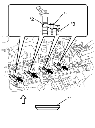
INSTALL NOZZLE HOLDER CLAMP SEAT
-
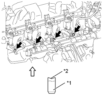
Text in Illustration *1 Nozzle holder clamp seat *2 Concave 
Upper Direction Install the 4 nozzle holder clamp seats onto the cylinder head.
Note
Install the nozzle holder clamp seats with the concave end facing up.
-
-
INSTALL NO. 1 NOZZLE HOLDER CLAMP
-
Text in Illustration *1 Washer *2 Nozzle holder clamp *3 Nozzle holder clamp seat Upper Direction Install the 4 nozzle holder clamps onto the injectors.
-
Set the washer on the nozzle holder clamp, as shown illustration.
Note
Install the washer in the correct direction.
-
Tighten the 4 nozzle holder clamp bolts.
- Torque:
- 19 N*m { 194 kgf*cm, 14 ft.*lbf }
-
-
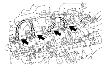
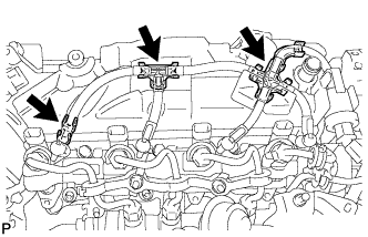
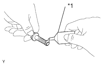
INSTALL NOZZLE LEAKAGE PIPE ASSEMBLY
-
Install the nozzle leakage pipe into each injector.
-
Make sure the lock bush is at top position.
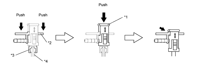
Text in Illustration *1 Lock Bush *2 Return Plug *3 Rest Arm *4 Injector -
Insert the rest arm into the injector and push both sides of the return plug until the rest arm engages with the injector, as shown in the illustration.
Tech Tips
Push the nozzle leakage pipe until it makes a click sound.
-
Push the lock bush until the it fits with the return plug, as shown in the illustration.
-
-
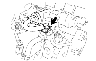
Connect the nozzle leakage pipe and install new retainer spring onto the supply pump.
-
-
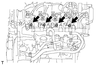
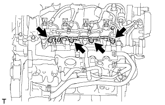
INSTALL NOZZLE LEAKAGE PIPE SET CLAMP
-
Install the 3 nozzle leakage pipe set clamps.
-
-
INSTALL NO. 2 INTAKE MANIFOLD INSULATOR
-
Install the No. 2 intake manifold insulator.
-
-
INSTALL GLOW PLUG ASSEMBLY
-
Clean the glow plug installation holes in the cylinder head.
-
Install the 4 glow plugs.
- Torque:
- 13 N*m { 127 kgf*cm, 9 ft.*lbf }
-
-
INSTALL NO. 1 GLOW PLUG CONNECTOR
-
Install the No. 1 glow plug connector with the 4 nuts.
- Torque:
- 2.2 N*m { 22 kgf*cm, 19 in.*lbf }
-
Install the 4 screw grommets.
-
-
INSTALL NO. 1 INJECTION PIPE SUB-ASSEMBLY
-
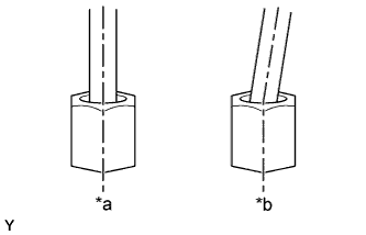
Text in Illustration *a Correct *b Incorrect Temporarily install 4 new injection pipes onto the injectors and common rail.
Note
Install the pipe and union nut vertically, not at a tilt.
-
Using a union nut wrench (17 mm), tighten the injection pipe union nut on the common rail, and then tighten the union nut on the injector.
- Torque:
- 28 N*m { 286 kgf*cm, 20 ft.*lbf }
Note
Use the formula to calculate special torque values for situations where a union nut wrench is combined with a torque wrench Click here.
-
-
INSTALL NO. 2 INJECTION PIPE SUB-ASSEMBLY
Tech Tips
Perform the same procedure as for injection pipe No. 1.
-
INSTALL NO. 3 INJECTION PIPE SUB-ASSEMBLY
Tech Tips
Perform the same procedure as for injection pipe No. 1.
-
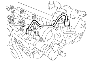
INSTALL NO. 1 INJECTION PIPE CLAMP
-
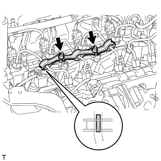
Install both sides of the No. 1 injection pipe clamp with the 2 nuts as shown in the illustration.
- Torque:
- 9.0 N*m { 92 kgf*cm, 80 in.*lbf }
-
-
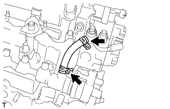
INSTALL NO. 2 INJECTION PIPE CLAMP
-
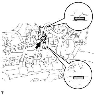
Install both sides of the No. 2 injection pipe clamp with the nut as shown in the illustration.
- Torque:
- 9.0 N*m { 92 kgf*cm, 80 in.*lbf }
-
-
INSTALL INTAKE AIR CONNECTOR WITH DIESEL THROTTLE BODY
-
Install the new gasket to the cylinder head.
-
Install the intake air connector with the diesel throttle body with the 2 bolts and 2 nuts.
- Torque:
- 23 N*m { 235 kgf*cm, 17 ft.*lbf }
-
-
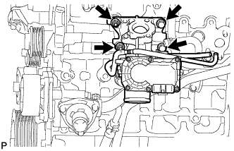
INSTALL ELECTRIC EGR CONTROL VALVE ASSEMBLY
-
Install a new gasket.
-
Text in Illustration *1 Adhesive Apply adhesive to the 2 bolts.
Adhesive Toyota Genuine Adhesive 1324, Three Bond 1324 or equivalent. -
Text in Illustration *1 EGR Control Valve Install the electric EGR control valve with the 2 bolts.
- Torque:
- 23 N*m { 235 kgf*cm, 17 ft.*lbf }
-
Connect the No. 3 water by-pass hose.
-
Connect the No. 4 water by-pass hose.
-
-
INSTALL HARNESS BRACKET
-
Install the harness bracket with the bolt.
- Torque:
- 10 N*m { 102 kgf*cm, 7 ft.*lbf }
-
Connect the vacuum hose to the vacuum pump.
-
-
INSTALL NO. 1 EGR COOLER BRACKET
-
Install the No. 1 EGR cooler bracket with the 2 bolts.
- Torque:
- 23 N*m { 235 kgf*cm, 17 ft.*lbf }
-
Connect the vacuum hose.
-
-
INSTALL NO. 5 ENGINE COVER
-
Align the hook and install the No. 5 engine cover onto the No. 1 EGR cooler bracket.
-
Engage the 2 claws.
-
-
INSTALL EGR WITH COOLER PIPE ASSEMBLY
-
Install 2 new gaskets.
-
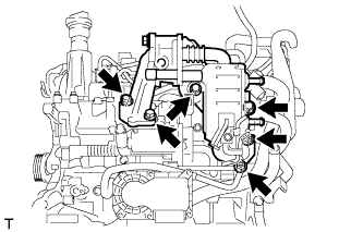
Install the EGR with cooler pipe assembly with the 4 bolts and 2 nuts.
- Torque:
- 23 N*m { 235 kgf*cm, 17 ft.*lbf }
-
Connect the No. 2 water by-pass hose.
-
Connect the No. 2 oil cooler hose.
-
Connect the 2 vacuum hoses and No. 1 oil hose.
-
Connect the No. 1 vacuum transmitting hose.
-
Connect the vacuum transmitting hose.
-
-
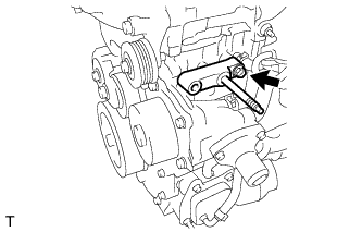
INSTALL GENERATOR BRACKET
-
Install the No. 1 generator bracket with the bolt.
- Torque:
- 40 N*m { 407 kgf*cm, 30 ft.*lbf }
-
-
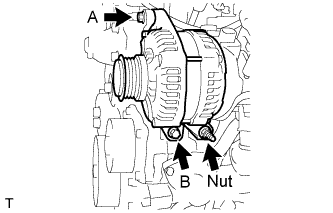
INSTALL GENERATOR ASSEMBLY
-
Install the generator with the 2 bolts and nut.
- Torque:
- Bolt A
- 21 N*m { 214 kgf*cm, 15 ft.*lbf }
- Bolt B, Nut
- 54 N*m { 551 kgf*cm, 40 ft.*lbf }
-
-
INSTALL TURBOCHARGER SUB-ASSEMBLY WITH EXHAUST MANIFOLD
Text in Illustration *1 Compressor Side
-
Install a new gasket to the turbocharger.
-
Temporarily tighten the turbo oil inlet pipe with the 2 nuts to the turbocharger.
-
Install 2 new gaskets to the cylinder head and cylinder block.
-
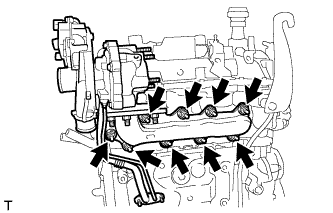
Install the turbocharger with the exhaust manifold with the 9 nuts.
- Torque:
- 43 N*m { 438 kgf*cm, 32 ft.*lbf }
-
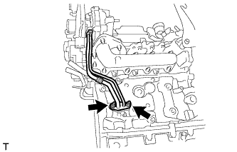
Temporarily tighten the turbo oil inlet pipe with the 2 nuts to the cylinder block.
-
Fully tighten the 4 nuts.
Tech Tips
Fully tighten the nuts on the turbocharger side before tightening the nuts on the cylinder block.
- Torque:
- Turbocharger Side
- 11 N*m { 112 kgf*cm, 8 ft.*lbf }
- Cylinder Block Side
- 9.0 N*m { 92 kgf*cm, 80 in.*lbf }
-
-
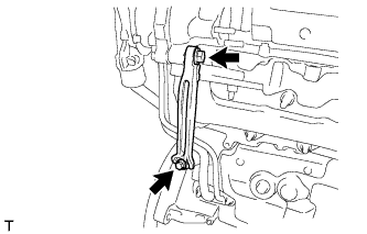
INSTALL TURBOCHARGER STAY
-
Temporarily tighten the turbocharger stay with the 2 bolts and nut.
-
Fully tighten the nut on the turbocharger side before tightening the bolts on the cylinder head side.
- Torque:
- 37 N*m { 377 kgf*cm, 27 ft.*lbf }
-
-
INSTALL NO. 2 TURBOCHARGER STAY
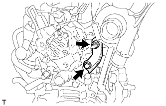
-
Temporarily tighten the No. 2 turbocharger stay with the bolt and nut.
-
Fully tighten the nut on the turbocharger side before tightening the bolt on the cylinder head side.
- Torque:
- 37 N*m { 377 kgf*cm, 27 ft.*lbf }
-
-
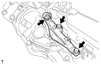
INSTALL MANIFOLD STAY
-
Install the manifold stay with the 2 bolts.
- Torque:
- 37 N*m { 377 kgf*cm, 27 ft.*lbf }
-
-
INSTALL NO. 1 TURBO INSULATOR
-
Install the No. 1 turbo insulator with the 2 bolts.
- Torque:
- 7.0 N*m { 71 kgf*cm, 62 in.*lbf }
-