БЛОК ДВИГАТЕЛЯ ПОВТОРНАЯ СБОРКА

-
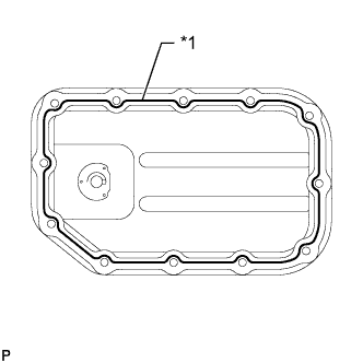
INSTALL OIL PAN SUB-ASSEMBLY
-
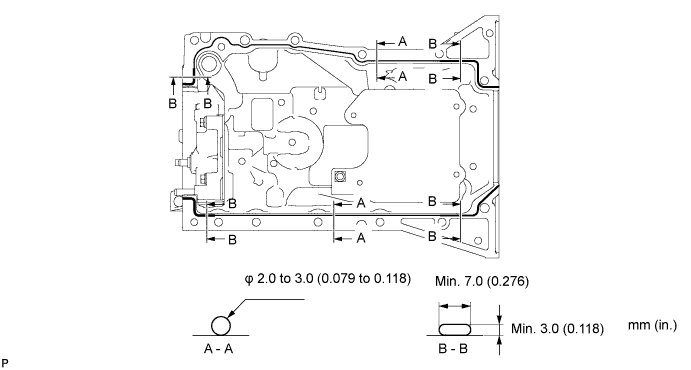
Apply a continuous bead of seal packing to the oil pan as illustrated.
Standard Seal Diameter Area Bead Size
mm (in.)
A - A 2.0 to 3.0
(0.079 to 0.118)
B - B Min. Width: 7.0 (0.2756)
Min. Height: 3.0 (0.1181)
Seal packing Toyota Genuine Seal Packing Black, Three Bond 1207B or equivalent Note
-
Remove any oil from the contact surface.
-
Install the oil pan within 3 minutes, and tighten the bolts within 15 minutes of applying the seal packing.
-
-
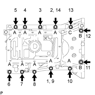
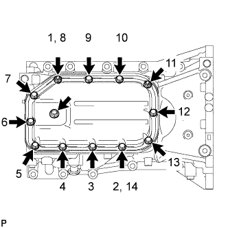
Using several steps, temporarily tighten the 12 bolts in the sequence shown in the illustration, and then tighten the bolts to the specified torque.
- Torque:
- 21 N*m { 214 kgf*cm, 15 ft.*lbf }
Bolt Length Bolt Length
mm (in.)
A 35 (1.378) B 143.7 (5.657) C 119 (4.685)
-
-
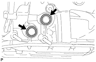
INSTALL ENGINE REAR OIL SEAL
-
Apply MP grease to a new oil seal lip.
Note
Keep the lip free of foreign matter.
-
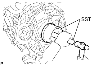
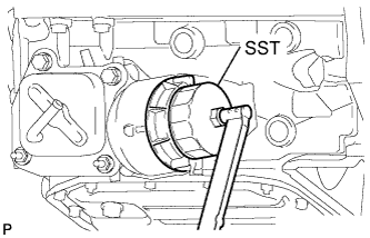
Using SST and a hammer, tap in the new oil seal until its surface is flush the cylinder block edge.
- SST
- 09223-15030
- 09950-70010 ( 09951-07100 )
Note
-
Tap the oil seal from the vertical position.
-
Wipe any extra grease off the crankshaft.
-
-
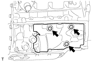
INSTALL ENGINE OIL LEVEL SENSOR
-
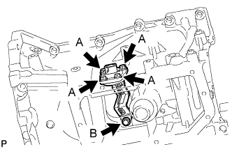
Temporarily tighten the oil level sensor with the 5 bolts.
-
Fully tighten the A bolts first, and then tighten bolt B.
- Torque:
- 9.0 N*m { 92 kgf*cm, 80 in.*lbf }
-
-
INSTALL NO. 2 OIL PAN SUB-ASSEMBLY
-
Text in Illustration *1 Seal Packing Apply a continuous bead of seal packing (Diameter 2.5 to 3.5 mm (0.098 to 0.138 in.)) to the No. 2 oil pan as illustrated.
Seal packing Toyota Genuine Seal Packing Black, Three Bond 1207B or equivalent Note
-
Remove any oil from the contact surface.
-
Install the oil pan within 3 minutes, and tighten the bolts within 10 minutes of applying the seal packing.
-
-
Temporarily tighten the No. 2 oil pan with the 10 bolts and 2 nuts.
-
Fully tighten the 10 bolts and 2 nuts, as shown in the illustration.
- Torque:
- 9.0 N*m { 92 kgf*cm, 80 in.*lbf }
-
Install a new gasket and oil pan drain plug.
- Torque:
- 38 N*m { 387 kgf*cm, 28 ft.*lbf }
-
-
INSTALL OIL PAN COVER SILENCER
-
Install the oil pan cover silencer with the 3 clips.
-
-
SET OIL FILTER BRACKET SUB-ASSEMBLY
-
Check and clean the oil filter bracket installation surface.
-
Install 2 new O-rings to the oil pan.
-
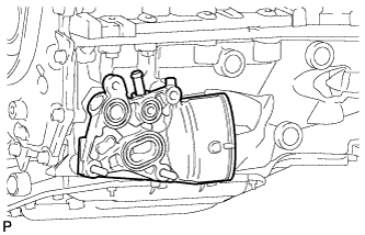
Set the oil filter bracket to the oil pan.
-
-
INSTALL OIL COOLER ASSEMBLY
-
Check and clean the oil cooler installation surface.
-
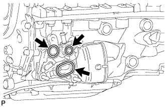
Install 2 new O-rings and a new gasket to the oil filter bracket.
-
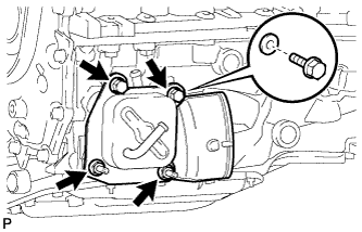
Temporarily tighten the oil cooler bracket and oil cooler with the spacer and 2 bolts and 2 nuts.
-
Fully tighten the 2 bolts and 2 nuts.
- Torque:
- 21 N*m { 214 kgf*cm, 15 ft.*lbf }
-
-
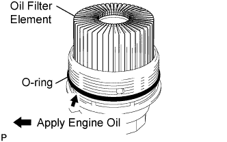
INSTALL OIL FILTER ELEMENT
-
Clean the inside of oil filter cap, threads, and O-ring groove.
-
Apply a small amount of engine oil to a new O-ring and install it to the oil filter cap.
-
Install a new oil filter element into the oil filter cap.
-
Remove any dirt or foreign matter from the contact surfaces of the oil filter cap (with oil filter element) and oil filter bracket.
-
Install the oil filter cap (with oil filter element) to the oil filter bracket.
-
-
INSTALL OIL FILTER CAP ASSEMBLY WITH ELEMENT
-
Using SST, tighten the oil filter cap.
- SST
- 09228-06501
- Torque:
- 25 N*m { 255 kgf*cm, 18 ft.*lbf }
-
-
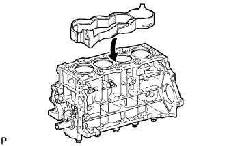
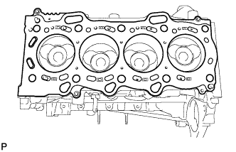
INSTALL CYLINDER BLOCK WATER JACKET SPACER
-
Install the cylinder block water jacket spacer to cylinder block.
-
-
INSTALL CYLINDER HEAD GASKET
-
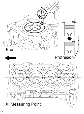
Inspect the protrusion height of the piston heads.
-
Place a dial indicator on the cylinder block as shown in the illustration.
Note
Make sure that the dial indicator is at right angles to the cylinder block top surface.
-
Measure the protrusion height of the piston head of each cylinder at 2 places as shown in the illustration.
-
-
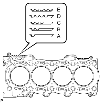
Select a new cylinder head gasket.
-
Select the highest protrusion height among the 8 measurements records. It is used to select a new cylinder head gasket.
Piston Protrusion Piston Protrusion mm (in.) Gasket Cutout Gasket Size 0.525 to 0.575
(0.020 to 0.023)
1 A 0.576 to 0.625
(0.023 to 0.025)
2 B 0.626 to 0.675
(0.025 to 0.027)
3 C 0.676 to 0.725
(0.027 to 0.029)
4 D 0.726 to 0.775
(0.029 to 0.031)
5 E
-
-
Install the cylinder head gasket.
-
Apply seal packing (Diameter 3.5 to 4.5 mm (0.138 to 0.177 in.)) to the cylinder block side as shown in the illustration.
Seal packing Toyota Genuine Seal Packing Black, Three Bond 1207B or equivalent Note
Remove any oil from the contact surface.
-
Place a new cylinder head gasket on the cylinder block with the Lot No. stamp facing upward.
-
Apply seal packing (Diameter 3.5 to 4.5 mm (0.138 to 0.177 in.)) to the top surface of the cylinder head again as shown in the illustration.
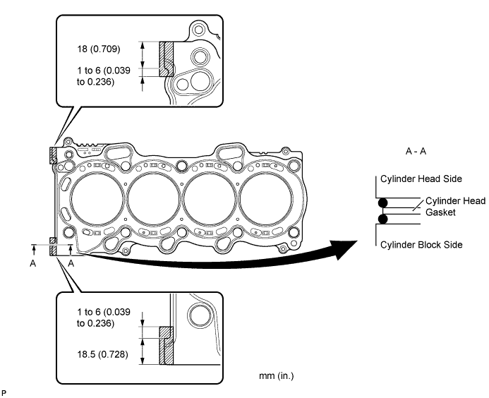
Seal packing Toyota Genuine Seal Packing Black, Three Bond 1207B or equivalent -
Install the cylinder head gasket onto the cylinder block.
Note
-
Remove any oil from the contact surface.
-
Install the cylinder head within 3 minutes, and tighten the bolts within 15 minutes of applying the seal packing.
-
-
-
-
INSTALL CYLINDER HEAD SUB-ASSEMBLY
Tech Tips
The cylinder head bolts are tightened in multiple steps.
-
Apply a light coat of engine oil to the threads of the cylinder head bolts.
-
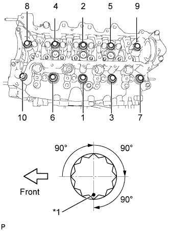
Text in Illustration *1 Paint Mark Using several passes, uniformly install and tighten the 10 cylinder head bolts and plate washers in the sequence shown in the illustration. (*1)
- Torque:
- 50 N*m { 510 kgf*cm, 37 ft.*lbf }
-
Mark the front of the cylinder head bolts with paint.
-
Using the same sequence as step (*1), retighten the cylinder head bolts by an additional 90° repeat it 2 more times.
-
Check that each paint mark is now 270° from the front.
-
-
INSTALL NO. 1 VALVE ROCKER ARM SUB-ASSEMBLY
-
Apply engine oil to the stem end caps, valve rocker arm pivot top surfaces and valve rocker arm roller portions.
-
Install the 8 valve rocker arms.
-
-
INSTALL CAMSHAFT
-
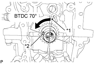
Text in Illustration *1 TDC Mark *2 Key Turn the crankshaft to set the key in the 70° BTDC position.
-
Apply engine oil to the camshaft journal portion and cam portion.
-
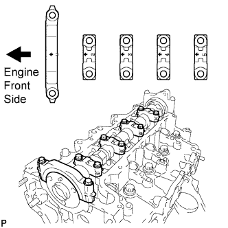
Examine the front marks and numbers and check that the sequence is as shown in the illustration. Then, temporarily tighten the camshaft with the camshaft bearing caps and bolts.
Note
Do not tilt the valve rocker arm when installing the camshaft onto the cylinder head.
-
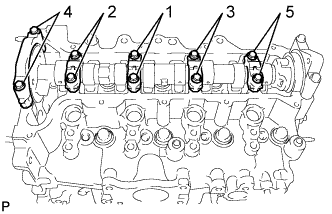
Using several steps, temporarily tighten the bolts in the sequence shown in the illustration, and then tighten the bolts to the specified torque.
- Torque:
- 19 N*m { 194 kgf*cm, 14 ft.*lbf }
-
-
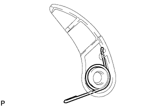
INSTALL CHAIN DAMPER SPRING
-
Install the chain damper spring to the chain tensioner plate.
-
-
INSTALL NO. 2 CHAIN SUB-ASSEMBLY
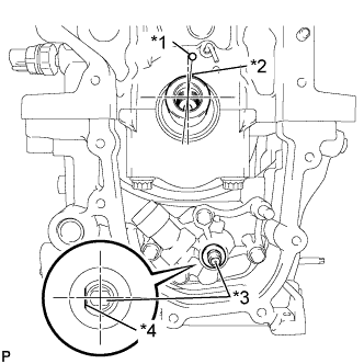
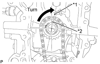
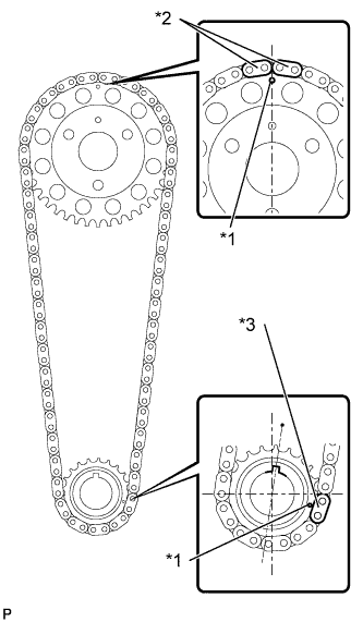
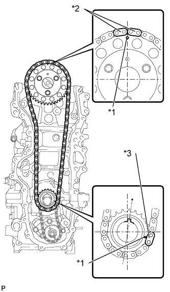
Text in Illustration *1 TDC Mark *2 Key *3 Oil Pump Shaft *4 Flat Faces
-
Align the crankshaft key with the TDC mark on the cylinder block.
-
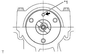
Rotate the oil pump shaft so that the flat faces left when viewing the cylinder block from the front.
-
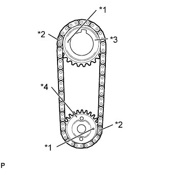
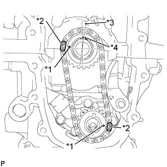
Text in Illustration *1 Timing Mark *2 Mark Link *3 Oil Pump Drive Gear *4 Oil Pump Drive Shaft Gear Align the orange mark links with the timing marks of each gear as shown in the illustration.
-
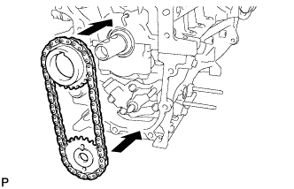
Install the sprockets onto the crankshaft and oil pump shaft with the chain wrapped on the gears.
-
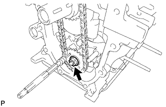
Insert a 4 mm (0.157 in.) diameter bar into the adjusting hole on the oil pump drive shaft gear to lock the gear in position, and then tighten the nut.
- Torque:
- 30 N*m { 306 kgf*cm, 22 ft.*lbf }
-
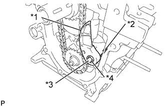
Text in Illustration *1 Tensioner Plate *2 Damper Spring *3 Pin *4 Pivot Hole Install the chain tensioner plate with the chain damper spring to the pin.
Note
-
Push the chain tensioner plate so that the area around the pivot hole reaches the base of the pin.
-
The end of the spring should contact the side of the oil pan so that tension is applied to the chain.
-
-
Text in Illustration *1 Timing Mark *2 Mark Link *3 TDC Mark *4 Key Check that the mark plate and timing mark are in the positions shown in the illustration.
-
-
INSTALL CHAIN SUB-ASSEMBLY
-
Text in Illustration *1 Straight Pin Turn the camshaft to set the straight pin in the position shown in the illustration.
-
Text in Illustration *1 TDC Mark *2 Key Turn the crankshaft to set the key in the position shown in the illustration.
-
Text in Illustration *1 Timing Mark *2 Orange Mark Plate *3 Yellow Mark Plate Align the chain's 2 orange mark plates with the timing mark on the camshaft timing sprocket, and the yellow mark plate with the timing mark on the crankshaft timing sprocket.
-
Text in Illustration *1 Timing Mark *2 Orange Mark Plate *3 Yellow Mark Plate Install the chain, camshaft timing sprocket and crankshaft sprocket together onto the engine.
-
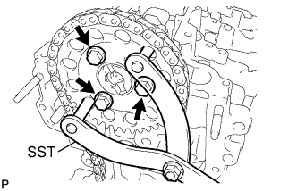
Using SST, fix the camshaft timing sprocket, and install the camshaft timing sprocket with the 3 bolts.
- SST
- 09960-10010 ( 09962-01000, 09963-01000 )
- Torque:
- 20 N*m { 204 kgf*cm, 15 ft.*lbf }
-
-
INSTALL NO. 1 CHAIN VIBRATION DAMPER
-
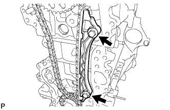
Install the chain vibration damper with the 2 bolts.
- Torque:
- 21 N*m { 214 kgf*cm, 15 ft.*lbf }
-
-
INSTALL CHAIN TENSIONER SLIPPER
-
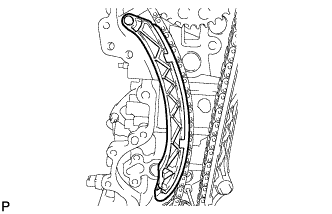
Install the chain tensioner slipper onto the cylinder block.
-
-
INSTALL NO. 1 CHAIN TENSIONER ASSEMBLY
-
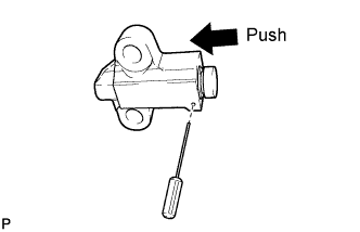
Push in the plunger until the groove is aligned with the tensioner hole, and then insert a 1.1 mm (0.043 in.) diameter bar.
-
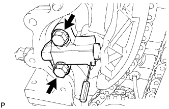
Install the chain tensioner with the 2 bolts.
- Torque:
- 21 N*m { 214 kgf*cm, 15 ft.*lbf }
-
Remove the 1.1 mm (0.043 in.) diameter bar from the chain tensioner.
-
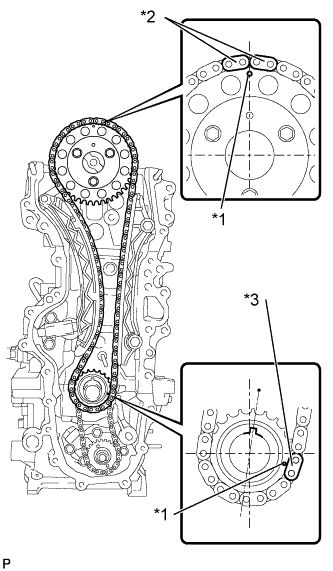
Text in Illustration *1 Timing Mark *2 Orange Mark Plate *3 Yellow Mark Plate Check that the mark plate and timing mark are in the positions shown in the illustration.
-
-
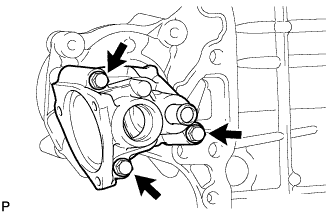
INSTALL WATER INLET HOUSING
-
Install a new gasket to the water inlet housing.
-
Install the water inlet housing to the timing chain cover with the 3 bolts.
- Torque:
- 9.1 N*m { 93 kgf*cm, 81 in.*lbf }
-
-
INSTALL TIMING CHAIN COVER SUB-ASSEMBLY
-
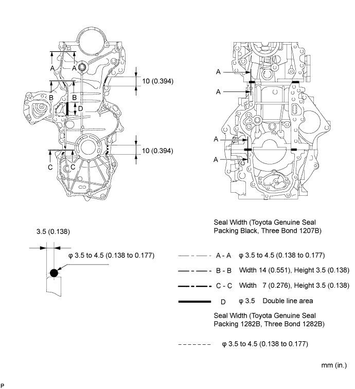
Apply seal packing to the engine body and oil pump as shown in the illustration below.
Note
-
Remove any oil from the contact surface.
-
Install the timing chain cover within 3 minutes, and tighten the bolts within 15 minutes of applying the seal packing.
Seal packing Water pump: Toyota Genuine Seal Packing 1282B, Three Bond 1282B or equivalent Other: Toyota Genuine Seal Packing Black, Three Bond 1207B or equivalent -
-
Install the timing chain cover with the 20 bolts and 2 nuts, as shown in the illustration.
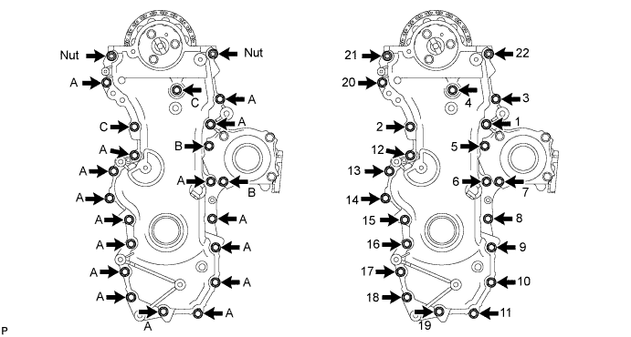
- Torque:
- Bolt A, B, Nut
- 21 N*m { 214 kgf*cm, 15 ft.*lbf }
- Bolt C
- 40 N*m { 408 kgf*cm, 30 ft.*lbf }
Bolt Length Bolt Length
mm (in.)
A 25 (0.984) B 35 (1.378) C 40 (1.575) Note
-
Make sure that the chain does not come into contact with the seal packing when installing the timing chain cover.
-
Install the engine mounting bracket RH and water pump within 10 minutes of installing the timing chain cover.
-
-
INSTALL CRANKSHAFT DAMPER SUB-ASSEMBLY
-
Align the key with the key groove of the crankshaft damper, and slide the crankshaft damper to the crankshaft.
-
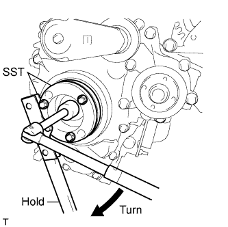
Using SST, secure the crankshaft damper.
- SST
- 09213-58014
- 09330-00021
-
Tighten the bolt to the specified torque.
- Torque:
- 210 N*m { 2141 kgf*cm, 155 ft.*lbf }
-
-
INSTALL NO. 2 TIMING CHAIN COVER
-
Install the No. 2 timing chain cover with the clip.
-
-
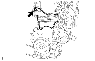
INSTALL ENGINE MOUNTING BRACKET RH
-
Temporarily tighten the engine mounting bracket with the 4 bolts.
-
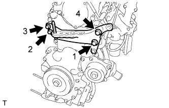
Fully tighten the 4 bolts, as shown in the illustration.
- Torque:
- 55 N*m { 561 kgf*cm, 41 ft.*lbf }
-
-
INSTALL ENGINE OIL PRESSURE SWITCH ASSEMBLY
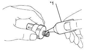
Text in Illustration *1 Adhesive
-
Apply adhesive to 2 or 3 threads of the oil pressure switch.
Adhesive TOYOTA Genuine Adhesive 1344, Three Bond 1344 or equivalent -
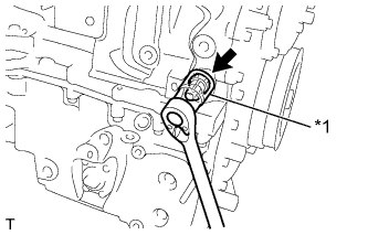
Text in Illustration *1 24 mm Deep Socket Wrench Using a 24 mm deep socket wrench, install the oil pressure switch.
- Torque:
- 15 N*m { 153 kgf*cm, 11 ft.*lbf }
-
-
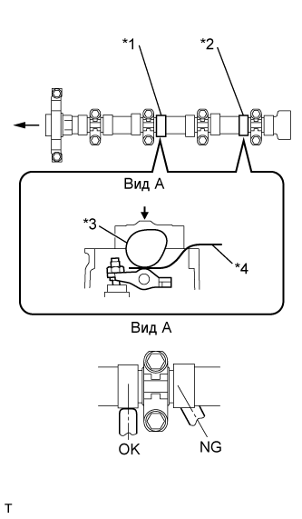
INSTALL THERMOSTAT
-
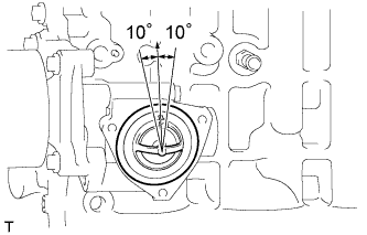
Install a new gasket onto the thermostat.
-
Install the thermostat with the jiggle valve facing upward.
Tech Tips
The jiggle valve should be set within 10° of the vertical position as illustrated.
-
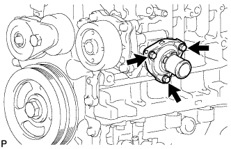
Install the water inlet with the 3 bolts.
- Torque:
- 9.0 N*m { 92 kgf*cm, 80 in.*lbf }
-
-
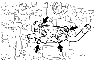
INSTALL WATER OUTLET SUB-ASSEMBLY
-
Install a new gasket to the cylinder head.
-
Install the water outlet with the 2 bolts and 2 nuts.
- Torque:
- 11 N*m { 112 kgf*cm, 8 in.*lbf }
-
-
INSTALL WATER TEMPERATURE SENSOR
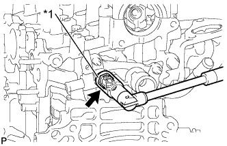
Text in Illustration *1 19 mm Deep Socket Wrench
-
Install a new gasket to the water temperature sensor.
-
Using a 19 mm deep socket wrench, install the water temperature sensor.
- Torque:
- 20 N*m { 204 kgf*cm, 15 ft.*lbf }
-
-
CHECK VALVE CLEARANCE
-
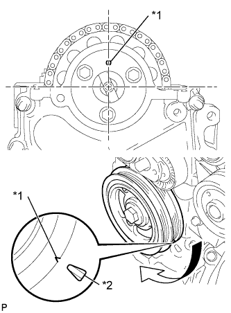
Обозначения на рисунке *1 Установочная метка *2 Метка ВМТ Установите цилиндр № 1 в ВМТ такта сжатия.
-
Поверните шкив коленчатого вала таким образом, чтобы совместить канавки на демпфере коленчатого вала и масляном насосе.
-
Убедитесь, что установочная метка ведущей звездочки распредвала расположена, как показано на рисунке.
Tech Tips
Если это не так, поверните демпфер коленчатого вала на 1 оборот (360°), чтобы совместить установочную метку и звездочку, как рассмотрено выше.
-
-
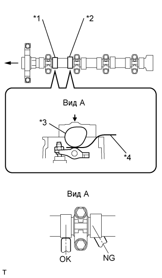
Обозначения на рисунке *1 № 1 на выпуске *2 № 2 на впуске *3 Распредвал *4 Плоский щуп Проверьте зазор в приводе выпускного клапана цилиндра № 1 и впускного клапана цилиндра № 2.
-
Щупом измерьте зазоры между и распредвалом и рычагом привода клапанов № 1.
Зазор в приводе клапанов (холодный двигатель) 0,11–0,17 мм (0,004–0,007 дюйма) для впуска 0,14–0,20 мм (0,006–0,008 дюйма) для выпуска Note
-
Вставьте плоский щуп в центре поверхности ролика параллельно рычагу привода клапана № 1.
-
Не прилагайте чрезмерного усилия к винту регулировки клапана при использовании таких регулировочных инструментов, как SST и отвертка.
Tech Tips
Если зазор не соответствует требованиям, запишите неудовлетворительный результат измерения, а затем отрегулируйте зазор в приводе клапанов.
-
-
-
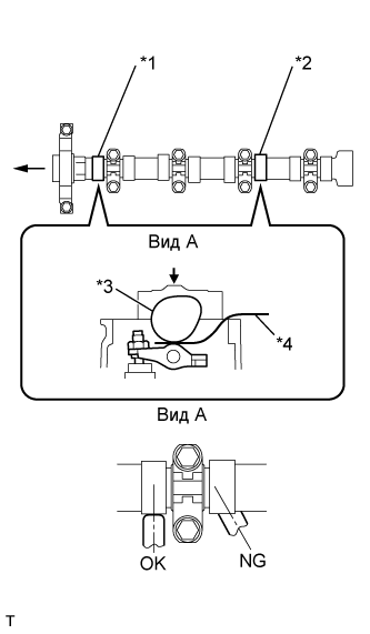
Обозначения на рисунке *1 № 1 на впуске *2 № 3 на выпуске *3 Распредвал *4 Плоский щуп Проверьте зазор в приводе впускного клапана цилиндра № 1 и выпускного клапана цилиндра № 3.
-
Поверните шкив коленчатого вала еще на 180° по часовой стрелке.
-
Щупом измерьте зазор между и распредвалом и рычагом привода клапанов № 1, как показано на рисунке.
Зазор в приводе клапанов (холодный двигатель) 0,11–0,17 мм (0,004–0,007 дюйма) для впуска 0,14–0,20 мм (0,006–0,008 дюйма) для выпуска Note
-
Вставьте плоский щуп в центре поверхности ролика параллельно рычагу привода клапана № 1.
-
Не прилагайте чрезмерного усилия к винту регулировки клапана при использовании регулировочных инструментов во время измерения или регулировки.
Tech Tips
Если зазор не соответствует требованиям, запишите неудовлетворительный результат измерения, а затем отрегулируйте зазор в приводе клапанов.
-
-
-
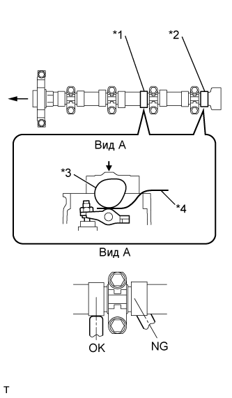
Обозначения на рисунке *1 № 3 на впуске *2 № 4 на выпуске *3 Распредвал *4 Плоский щуп Проверьте зазоры в приводах впускного клапана цилиндра № 3 и выпускного клапана цилиндра № 4.
-
Поверните шкив коленчатого вала еще на 180° по часовой стрелке.
-
Щупом измерьте зазор между и распредвалом и рычагом привода клапанов № 1, как показано на рисунке.
Зазор в приводе клапанов (холодный двигатель) 0,11–0,17 мм (0,004–0,007 дюйма) для впуска 0,14–0,20 мм (0,006–0,008 дюйма) для выпуска Note
-
Вставьте плоский щуп в центре поверхности ролика параллельно рычагу привода клапана № 1.
-
Не прилагайте чрезмерного усилия к винту регулировки клапана при использовании регулировочных инструментов во время измерения или регулировки.
Tech Tips
Если зазор не соответствует требованиям, запишите неудовлетворительный результат измерения, а затем отрегулируйте зазор в приводе клапанов.
-
-
-
Обозначения на рисунке *1 № 2 на выпуске *2 № 4 на впуске *3 Распредвал *4 Плоский щуп Проверьте зазоры в приводах впускного клапана цилиндра № 2 и впускного клапана цилиндра № 4.
-
Поверните шкив коленчатого вала еще на 180° по часовой стрелке.
-
Щупом измерьте зазоры между и распредвалом и рычагом привода клапанов № 1.
Зазор в приводе клапанов (холодный двигатель) 0,11–0,17 мм (0,004–0,007 дюйма) для впуска 0,14–0,20 мм (0,006–0,008 дюйма) для выпуска Note
-
Вставьте плоский щуп в центре поверхности ролика параллельно рычагу привода клапана № 1.
-
Не прилагайте чрезмерного усилия к винту регулировки клапана при использовании регулировочных инструментов во время измерения или регулировки.
Tech Tips
Если зазор не соответствует требованиям, запишите неудовлетворительный результат измерения, а затем отрегулируйте зазор в приводе клапанов.
-
-
-
-
ADJUST VALVE CLEARANCE
-
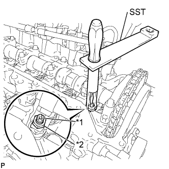
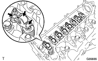
Обозначения на рисунке *1 Регулировочный винт *2 Контргайка С помощью SST и отвертки ослабьте гайку регулировки клапана, удерживая винт регулировки клапана на месте.
- SST
- 09248-56010
-
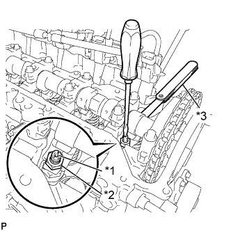
Обозначения на рисунке *1 Регулировочный винт *2 Контргайка *3 Плоский щуп Отрегулируйте зазор в приводе клапанов (на впуске).
-
Вставьте плоский щуп (0,14 мм (0,006 дюйма)) между распредвалом и рычагом привода клапана № 1, и поверните винт регулировки клапана для регулировки.
Зазор в приводе клапанов (холодный двигатель) 0,14 мм (0,006 дюйма) -
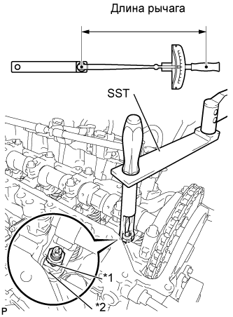
Обозначения на рисунке *1 Регулировочный винт *2 Контргайка С помощью SST и отвертки затяните гайку регулировки клапана, удерживая винт регулировки клапана на месте.
- Torque:
- При использовании SST
- 13 Н*м { 133 кгс*см, 10 фунт-сила-дюймов }
- Без использования SST
- 20 Н*м { 204 кгс*см, 15 фунт-сила-дюймов }
Tech Tips
-
Данное значение крутящего момента получено при использовании динамометрического ключа с длиной рычага 300 мм (11,81 дюйма) и SST с длиной рычага 150 мм (5,91 дюйма) (см. стр. Click here).
-
Данное значение крутящего момента действительно в случае, если SST установлен параллельно динамометрическому ключу.
-
-
Отрегулируйте зазор в приводе клапанов (на выпуске).
Зазор в приводе клапанов (холодный двигатель) 0,17 мм (0,007 дюйма) Tech Tips
Выполните такую же процедуру, что и для регулировки зазора в приводе клапанов со стороны впуска.
-
-
INSTALL CYLINDER HEAD COVER SUB-ASSEMBLY
-
Install the cylinder head gasket onto the cylinder head cover.
-
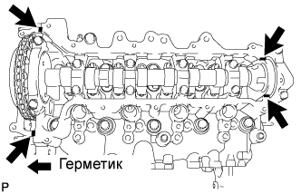
Apply seal packing to the 4 locations shown in the illustration, and then install the cylinder head cover.
Seal packing Toyota Genuine Seal Packing Black, Three Bond 1207B or equivalent Note
-
Remove any oil from the contact surface.
-
Install the cylinder head cover within 3 minutes, and tighten the bolts within 15 minutes of applying the seal packing.
-
-
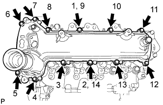
Temporarily tighten the cylinder head cover with the 12 bolts.
-
Fully tighten the 12 bolts, as shown in the illustration.
- Torque:
- 11 N*m { 112 kgf*cm, 8 ft.*lbf }
-
-
INSTALL OIL FILLER CAP SUB-ASSEMBLY
-
Install the oil filler cap gasket onto the oil filler cap.
-
Install the oil filler cap onto the cylinder head cover.
-