ПРОКЛАДКА ГОЛОВКИ БЛОКА ЦИЛИНДРОВ СНЯТИЕ

-
REMOVE ENGINE ASSEMBLY
-
Remove the engine assembly Click here.
-
-
REMOVE NO. 1 TURBO INSULATOR
-
Remove the 2 bolts and the No. 1 turbo insulator.
-
-
REMOVE TURBOCHARGER STAY
Remove the 2 bolts, nut and the turbocharger stay.
-
REMOVE NO. 2 TURBOCHARGER STAY
-
Remove the bolt, nut and the No. 2 turbocharger stay.
-
-
REMOVE MANIFOLD STAY
-
Remove the 2 bolts and manifold stay.
-
-
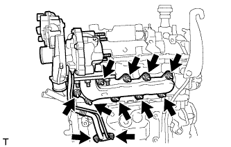
REMOVE TURBOCHARGER SUB-ASSEMBLY WITH EXHAUST MANIFOLD
-
Remove the 11 nuts and the turbocharger with the exhaust manifold.
-
Remove the 2 gaskets from the cylinder head and cylinder block.
-
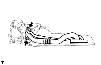
Remove the 2 nuts and the turbo oil inlet pipe from the turbocharger.
-
Remove the gasket from the turbocharger.
-
-
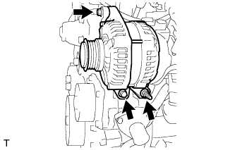
REMOVE GENERATOR ASSEMBLY
-
Remove the 2 bolts, nut and generator.
-
-
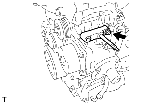
REMOVE GENERATOR BRACKET
-
Remove the bolt and the generator bracket.
-
-
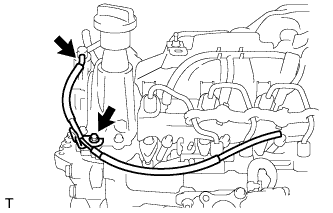
REMOVE EGR WITH COOLER PIPE ASSEMBLY
-
Disconnect the vacuum transmitting hose.
-
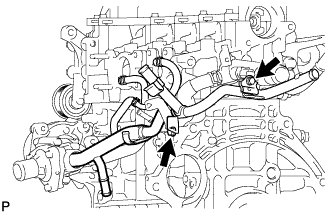
Disconnect the No. 1 vacuum transmitting hose.
-
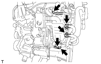
Disconnect the 2 vacuum hoses and No. 1 oil hose.
-
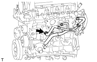
Disconnect the No. 2 oil cooler hose.
-
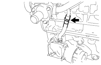
Disconnect the No. 2 water by-pass hose.
-
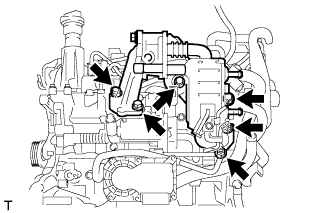
Remove the 4 bolts, 2 nuts and the EGR with cooler pipe assembly.
-
Remove the 2 gaskets from the cylinder head and the electric EGR control valve.
-
-
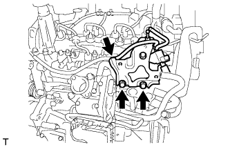
REMOVE NO. 1 EGR COOLER BRACKET
-
Disconnect the vacuum hose.
-
Remove the 2 bolts and the No. 1 EGR cooler bracket.
-
-
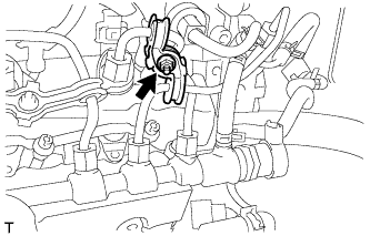
REMOVE HARNESS BRACKET
-
Disconnect the vacuum hose from the vacuum pump.
-
Remove the bolt and harness bracket.
-
-
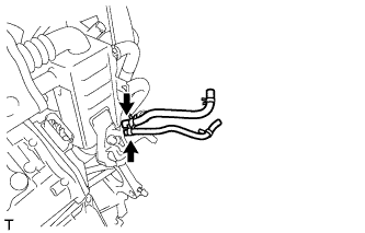
REMOVE ELECTRIC EGR CONTROL VALVE ASSEMBLY
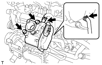
-
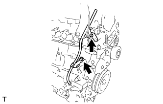
Disconnect the No. 4 water by-pass hose.
-
Disconnect the No. 3 water by-pass hose.
-
Remove the 2 bolts and the electric EGR control valve.
-
Remove the gasket from the intake air connector.
-
-
REMOVE INTAKE AIR CONNECTOR WITH THROTTLE BODY ASSEMBLY
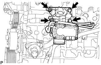
-
Remove the 2 bolts, 2 nuts and the intake air connector with the diesel throttle body.
-
Remove the gasket from the cylinder head.
-
-
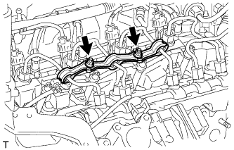
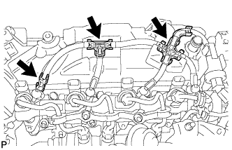
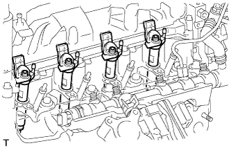
REMOVE NO. 2 INJECTION PIPE CLAMP
-
Remove the nut and both sides of the No. 2 injection pipe clamp.
-
-
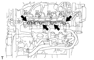
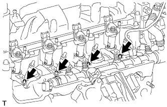
REMOVE NO. 1 INJECTION PIPE CLAMP
-
Remove the 2 nuts and both sides of the No. 1 injection pipe clamp.
-
-
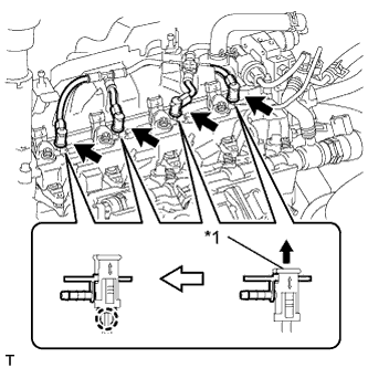
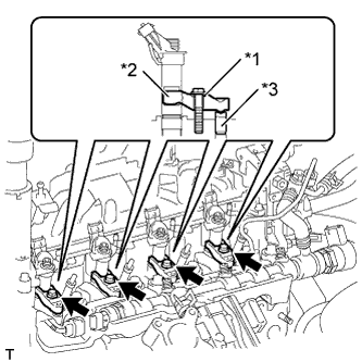
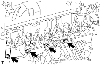
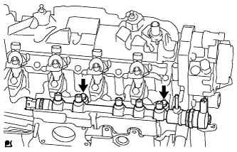
REMOVE NO. 1 INJECTION PIPE SUB-ASSEMBLY
-
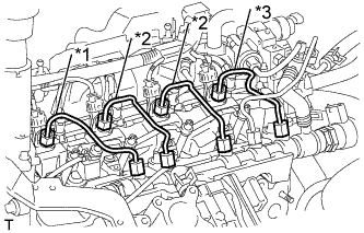
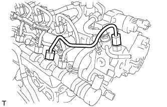
Text in Illustration *1 No. 1 Injection Pipe *2 No. 2 Injection Pipe *3 No. 3 Injection Pipe Using a union nut wrench (17 mm), separate the union nut from the injector first.
-
Then remove the union nut from the common rail, and remove the injection pipe.
-
After removing the injection pipe, cover the common rail with vinyl tape and cover the injector inlet with a vinyl or plastic bag in order to prevent dust and foreign matter from entering.
-
-
REMOVE NO. 2 INJECTION PIPE SUB-ASSEMBLY
Tech Tips
Perform the same procedure as for injection pipe No. 1.
-
REMOVE NO. 3 INJECTION PIPE SUB-ASSEMBLY
Tech Tips
Perform the same procedure as for injection pipe No. 1.
-
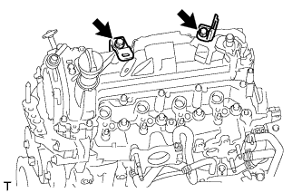
REMOVE NO. 1 GLOW PLUG CONNECTOR
-
Remove the 4 screw grommets.
-
Remove the 4 nuts and the No. 1 glow plug connector.
-
-
REMOVE GLOW PLUG ASSEMBLY
-
Remove the 4 glow plugs.
-
-
REMOVE NO. 2 INTAKE MANIFOLD INSULATOR
-
Remove the No. 2 intake manifold insulator.
-
-
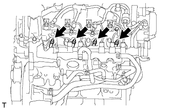
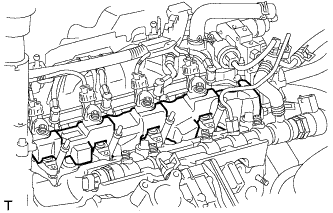
REMOVE NOZZLE LEAKAGE PIPE SET CLAMP
-
Remove the 3 nozzle leakage pipe set clamps.
-
-
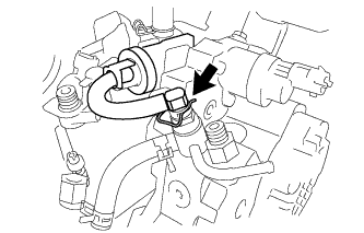
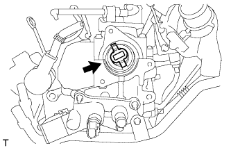
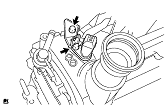
REMOVE NOZZLE LEAKAGE PIPE ASSEMBLY
-
Remove the retainer spring disconnect the nozzle leakage pipe.
-
Text in Illustration *1 Lock Bush Pull up the lock bush as shown in the illustration and remove the nozzle leakage pipe.
Note
Do not remove the nozzle leakage pipe by pulling the hose. Remove by holding the lock bush.
-
-
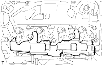
REMOVE NO. 1 NOZZLE HOLDER CLAMP
-
Text in Illustration *1 Washer *2 Nozzle holder clamp *3 Nozzle holder clamp seat Remove the 4 bolts, 4 washers, and 4 nozzle holder clamps.
-
-
REMOVE NOZZLE HOLDER CLAMP SEAT
-
Remove the 4 nozzle holder clamp seats from the cylinder head.
-
-
REMOVE INJECTOR ASSEMBLY
-
Remove the 4 injectors from the cylinder head.
Tech Tips
-
Each injector assembly has its own fuel injection part number. When replacing the injectors, store them in the correct order so that they can be returned to their original locations when reassembled.
-
Arrange the injectors, clamps, washers, bolts and clamp seats in the correct order.
-
-
-
REMOVE INJECTION NOZZLE SEAT
-
Remove the 4 injection nozzle seats from the injector or cylinder head.
Tech Tips
When removing the injector, check that the injector nozzle seat is either attached to the injector, or remains in the cylinder head.
-
-
REMOVE FUEL INLET PIPE SUB-ASSEMBLY
-
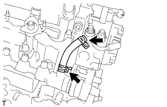
Using a wrench (17 mm), hold the supply pump nut, and using a union nut wrench (17 mm), separate the union nut from the supply pump first.
-
Then remove the union nut from the common rail, and remove the fuel inlet pipe.
-
After removing the fuel inlet pipe, cover the common rail with vinyl tape and cover the injector inlet with a vinyl or plastic bag in order to prevent dust and foreign matter from entering.
-
-
REMOVE NO. 2 FUEL HOSE
-
Remove the No. 2 fuel hose.
-
-
REMOVE SUPPLY PUMP ASSEMBLY
-
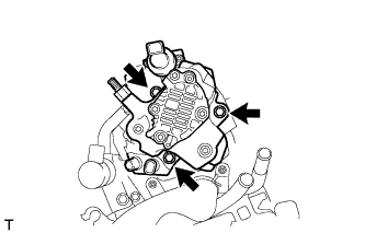
Remove the 3 bolts and supply pump.
-
Remove the O-ring.
-
-
REMOVE SUPPLY PUMP DRIVE COUPLING
-
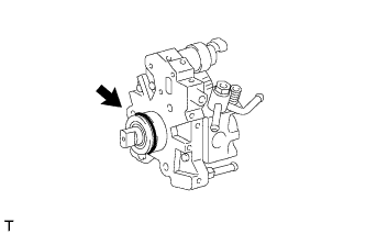
Remove the supply pump driving coupling.
Note
When removing the supply pump, make sure that the drive coupling does not fall off, as it can be easily removed. If the drive coupling falls off, replace it with a new one.
-
-
REMOVE COMMON RAIL ASSEMBLY
-
Remove the 2 bolts and common rail.
Note
Do not remove the fuel pressure sensor or fuel pressure regulator.
-
-
REMOVE NO. 1 INTAKE MANIFOLD INSULATOR
-
Remove the No. 1 intake manifold insulator.
-
-
REMOVE NO. 2 CYLINDER HEAD COVER
-
Remove the 2 bolts and the 2 harness brackets.
-
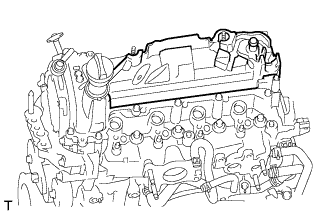
Remove the No. 2 cylinder head cover.
-
-
REMOVE NO. 2 OIL COOLER HOSE
-
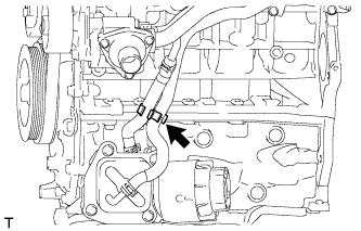
Remove the hose clamp.
-
Disconnect the 2 clamps and remove the No. 2 oil cooler hose.
-
-
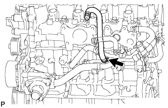
REMOVE NO. 4 WATER BY-PASS HOSE
-
Remove the No. 4 water by-pass hose.
-
-
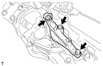
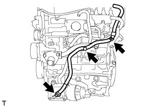
REMOVE WATER BY-PASS PIPE SUB-ASSEMBLY
-
Disconnect the oil cooler hose.
-
Disconnect the water by-pass hose.
-
Remove the 2 bolts and the water by-pass pipe.
-
Remove the O-ring from the water by-pass pipe.
-
-
REMOVE ENGINE OIL LEVEL DIPSTICK
-
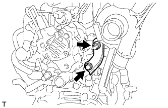
REMOVE OIL LEVEL DIPSTICK GUIDE
-
Remove the 2 bolts and the oil level dipstick guide.
-
Remove the O-ring from the oil level dipstick guide.
-
-
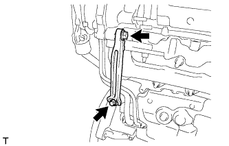
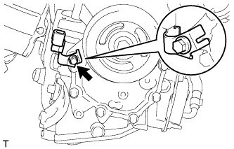
REMOVE CAMSHAFT POSITION SENSOR
-
Remove the bolt and harness bracket.
-
Remove the bolt and camshaft position sensor.
-
-
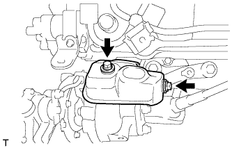
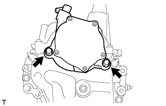
REMOVE VACUUM PUMP ASSEMBLY
-
Remove the 2 bolts and vacuum pump.
-
Remove the 2 O-rings from the vacuum pump.
-
-
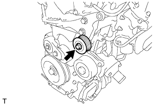
REMOVE IDLER PULLEY SUB-ASSEMBLY
-
Remove the bolt and idler pulley.
-
-
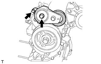
REMOVE V-RIBBED BELT TENSIONER ASSEMBLY
-
Remove the 2 bolts and the V-ribbed belt tensioner.
-
-
REMOVE HARNESS BRACKET (w/o Air Conditioning System)
-
Remove the bolt and harness bracket.
-
-
REMOVE CYLINDER HEAD COVER SUB-ASSEMBLY
-
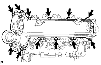
Remove the 12 bolts and the cylinder head cover.
-
Remove the cylinder head cover gasket from the cylinder head cover.
-
-
REMOVE ENGINE MOUNTING BRACKET RH
-
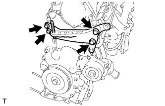
Remove the 4 bolts and the engine mounting bracket.
-
-
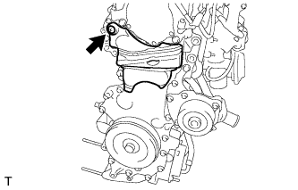
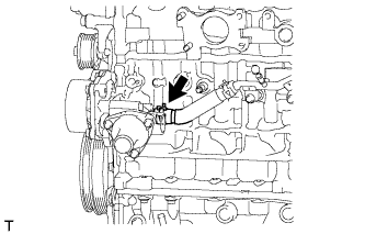
REMOVE NO. 2 TIMING CHAIN COVER
-
Remove the clip and the No. 2 timing chain cover.
-
-
REMOVE CRANKSHAFT DAMPER SUB-ASSEMBLY
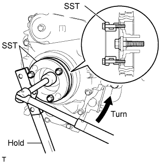
-
Using SST, hold the crankshaft damper and loosen the crankshaft bolt.
- SST
- 09213-58014
- 09330-00021
-
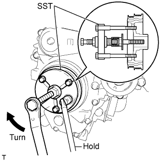
Using SST, remove the crankshaft pulley bolt and the crankshaft pulley.
- SST
- 09950-30012 ( 09951-03010, 09953-03010, 09956-03020 )
-
-
DISCONNECT WATER INLET HOSE LH
-
Disconnect the water inlet hose LH.
-
-
REMOVE TIMING CHAIN COVER SUB-ASSEMBLY
-
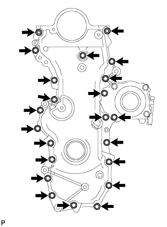
Remove the 20 bolts and the 2 nuts.
-
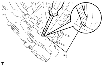
Text in Illustration *1 Protective Tape Using a screwdriver with its tip wrapped in protective tape, remove the timing chain cover by prying between the cylinder head and cylinder block.
Note
Do not damage the contact surfaces of the timing chain cover, cylinder head or cylinder block.
-
-
REMOVE NO. 1 CHAIN TENSIONER ASSEMBLY
Note
Do not rotate the crankshaft with the chain tensioner removed.
-
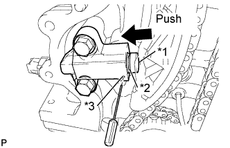
Text in Illustration *1 Plunger *2 Groove *3 Hole Push in the plunger until the groove is aligned with the tensioner hole, and then insert a 1.1 mm (0.043 in.) diameter bar.
-
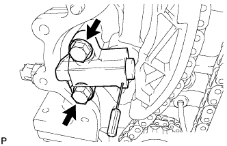
Remove the 2 bolts and the No. 1 chain tensioner.
-
-
REMOVE CHAIN TENSIONER SLIPPER
-
Remove the chain tensioner.
-
-
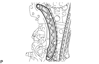
REMOVE NO. 1 CHAIN VIBRATION DAMPER
-
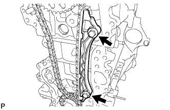
Remove the 2 bolts and the No. 1 chain vibration damper.
-
-
REMOVE CHAIN SUB-ASSEMBLY
-
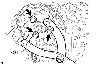
Using SST, hold the camshaft timing sprocket.
- SST
- 09960-10010 ( 09962-01000, 09963-01000 )
-
Remove the 3 bolts and the camshaft timing sprocket.
-
Remove the camshaft timing sprocket, crankshaft timing sprocket and chain together.
-
-
REMOVE CAMSHAFT
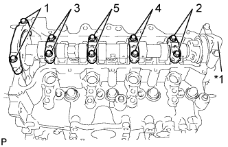
Text in Illustration *1 No. 3 Camshaft Bearing Cap
-
Remove the 10 bolts from the camshaft bearing caps by loosening them in the sequence shown in the illustration, and then remove the 5 camshaft bearing caps.
-
Remove the camshaft.
Note
-
Using several steps, uniformly loosen the bolts while keeping the camshaft level.
-
Do not remove the No. 3 camshaft bearing cap.
-
-
-
REMOVE NO. 1 VALVE ROCKER ARM SUB-ASSEMBLY
-
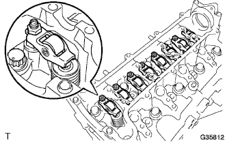
Remove the No. 1 valve rocker arm from the cylinder head.
-
-
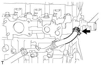
DISCONNECT WATER INLET HOSE RH
-
Disconnect the water inlet hose RH.
-
-
REMOVE CYLINDER HEAD SUB-ASSEMBLY
-
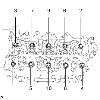
Using several steps, loosen the 10 bolts in the sequence shown in the illustration, and then remove the bolts and washers.
Note
-
When removing the bolts, do not drop the washers into the engine.
-
Removing the cylinder head bolts in the wrong order may cause damage to the cylinder head.
-
-
Remove the cylinder head.
-
-
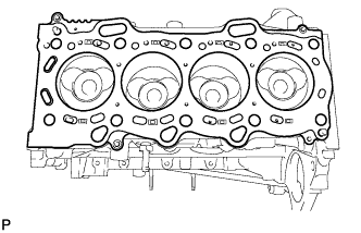
REMOVE CYLINDER HEAD GASKET
-
Remove the cylinder head gasket.
-