РАСПРЕДВАЛ УСТАНОВКА

-
INSTALL CAMSHAFT
-
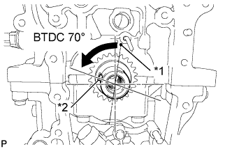
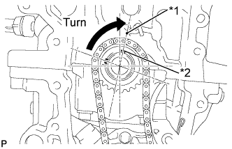
Text in Illustration *1 TDC Mark *2 Key Turn the crankshaft to set the key in the 70° BTDC position.
-
Apply engine oil to the camshaft journal portion and cam portion.
-
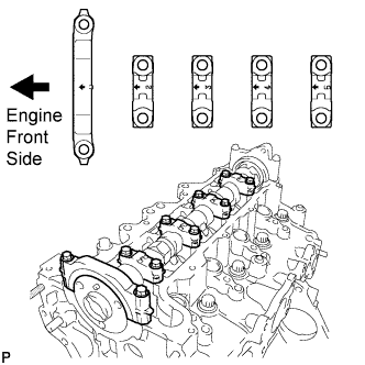
Examine the front marks and numbers and check that the sequence is as shown in the illustration. Then, temporarily tighten the camshaft with the camshaft bearing caps and bolts.
Note
Do not tilt the valve rocker arm when installing the camshaft onto the cylinder head.
-
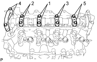
Using several steps, temporarily tighten the bolts in the sequence shown in the illustration, and then tighten the bolts to the specified torque.
- Torque:
- 19 N*m { 194 kgf*cm, 14 ft.*lbf }
-
-
INSTALL CHAIN SUB-ASSEMBLY
-
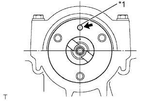
Text in Illustration *1 Straight Pin Turn the camshaft to set the straight pin in the position shown in the illustration.
-
Text in Illustration *1 TDC Mark *2 Key Turn the crankshaft to set the key in the position shown in the illustration.
-
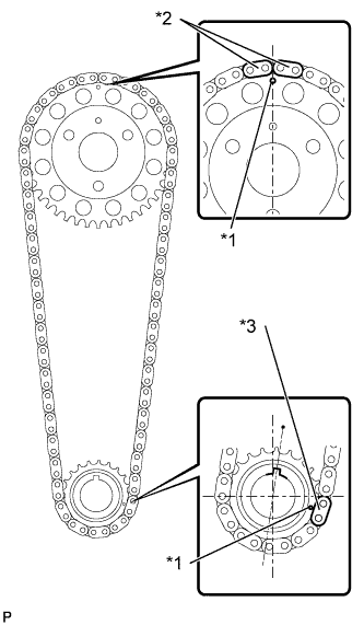
Text in Illustration *1 Timing Mark *2 Orange Mark Plate *3 Yellow Mark Plate Align the chain's 2 orange mark plates with the timing mark on the camshaft timing sprocket, and the yellow mark plate with the timing mark on the crankshaft timing sprocket.
-
Text in Illustration *1 Timing Mark *2 Orange Mark Plate *3 Yellow Mark Plate Install the chain, camshaft timing sprocket and crankshaft sprocket together onto the engine.
-
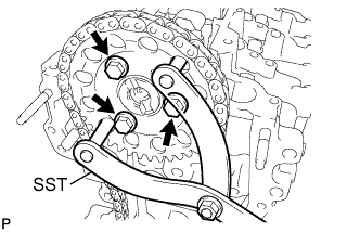
Using SST, fix the camshaft timing sprocket, and install the camshaft timing sprocket with the 3 bolts.
- SST
- 09960-10010 ( 09962-01000, 09963-01000 )
- Torque:
- 20 N*m { 204 kgf*cm, 15 ft.*lbf }
-
-
INSTALL NO. 1 CHAIN VIBRATION DAMPER
-
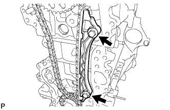
Install the chain vibration damper with the 2 bolts.
- Torque:
- 21 N*m { 214 kgf*cm, 15 ft.*lbf }
-
-
INSTALL CHAIN TENSIONER SLIPPER
-
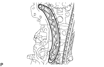
Install the chain tensioner slipper onto the cylinder block.
-
-
INSTALL NO. 1 CHAIN TENSIONER ASSEMBLY
-
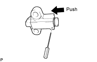
Push in the plunger until the groove is aligned with the tensioner hole, and then insert a 1.1 mm (0.043 in.) diameter bar.
-
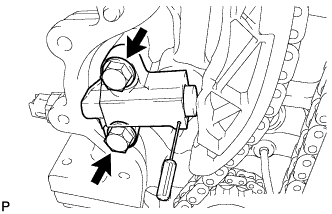
Install the chain tensioner with the 2 bolts.
- Torque:
- 21 N*m { 214 kgf*cm, 15 ft.*lbf }
-
Remove the 1.1 mm (0.043 in.) diameter bar from the chain tensioner.
-
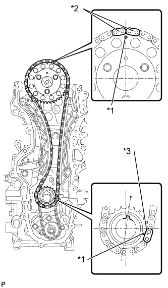
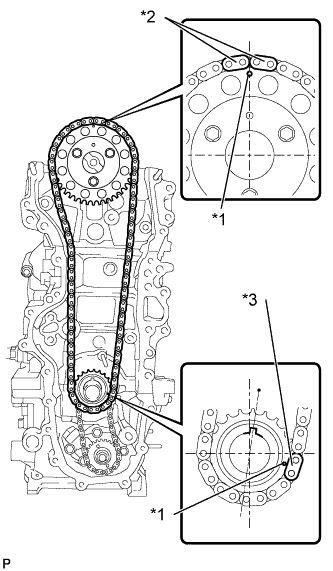
Text in Illustration *1 Timing Mark *2 Orange Mark Plate *3 Yellow Mark Plate Check that the mark plate and timing mark are in the positions shown in the illustration.
-
-
INSTALL TIMING CHAIN COVER SUB-ASSEMBLY
-
Install the No. 2 timing chain cover with the clip.
-
-
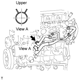
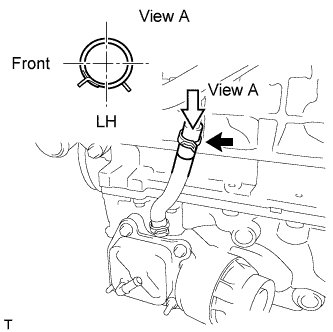
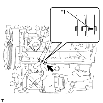
CONNECT WATER INLET HOSE LH
-
Connect the water inlet hose LH.
Tech Tips
The clip at the water inlet housing can be installed in any orientation, as long it does not contact any of the surrounding parts.
-
-
INSTALL CRANKSHAFT DAMPER SUB-ASSEMBLY
-
Align the key with the key groove of the crankshaft damper, and slide the crankshaft damper to the crankshaft.
-
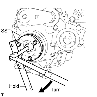
Using SST, secure the crankshaft damper.
- SST
- 09213-58014
- 09330-00021
-
Tighten the bolt to the specified torque.
- Torque:
- 210 N*m { 2141 kgf*cm, 155 ft.*lbf }
-
-
INSTALL NO. 2 TIMING CHAIN COVER
-
Install the No. 2 timing chain cover with the clip.
-
-
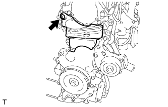
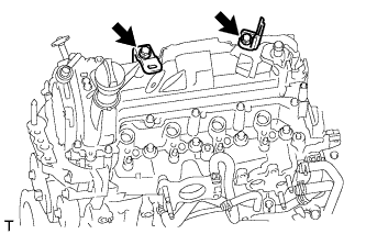
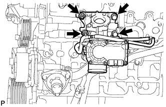
INSTALL ENGINE MOUNTING BRACKET RH
-
Temporarily tighten the engine mounting bracket with the 4 bolts.
-
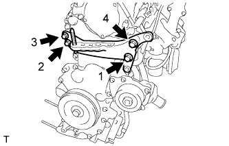
Fully tighten the 4 bolts, as shown in the illustration.
- Torque:
- 55 N*m { 561 kgf*cm, 41 ft.*lbf }
-
-
CHECK VALVE CLEARANCE
-
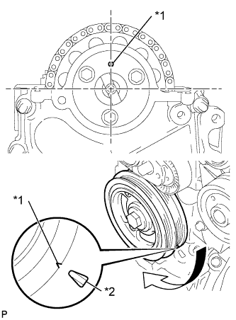
Обозначения на рисунке *1 Установочная метка *2 Метка ВМТ Установите цилиндр № 1 в ВМТ такта сжатия.
-
Поверните шкив коленчатого вала таким образом, чтобы совместить канавки на демпфере коленчатого вала и масляном насосе.
-
Убедитесь, что установочная метка ведущей звездочки распредвала расположена, как показано на рисунке.
Tech Tips
Если это не так, поверните демпфер коленчатого вала на 1 оборот (360°), чтобы совместить установочную метку и звездочку, как рассмотрено выше.
-
-
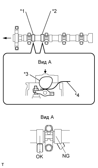
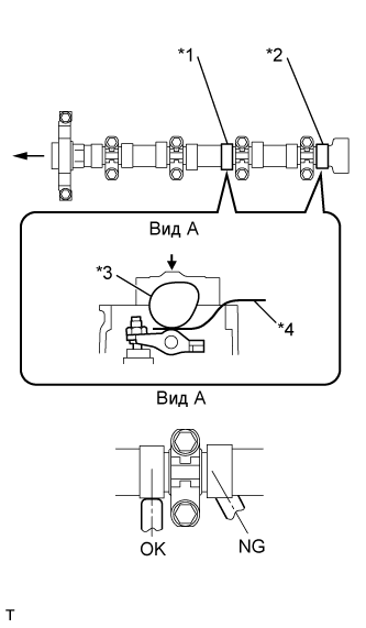
Обозначения на рисунке *1 № 1 на выпуске *2 № 2 на впуске *3 Распредвал *4 Плоский щуп Проверьте зазор в приводе выпускного клапана цилиндра № 1 и впускного клапана цилиндра № 2.
-
Щупом измерьте зазоры между и распредвалом и рычагом привода клапанов № 1.
Зазор в приводе клапанов (холодный двигатель) 0,11–0,17 мм (0,004–0,007 дюйма) для впуска 0,14–0,20 мм (0,006–0,008 дюйма) для выпуска Note
-
Вставьте плоский щуп в центре поверхности ролика параллельно рычагу привода клапана № 1.
-
Не прилагайте чрезмерного усилия к винту регулировки клапана при использовании таких регулировочных инструментов, как SST и отвертка.
Tech Tips
Если зазор не соответствует требованиям, запишите неудовлетворительный результат измерения, а затем отрегулируйте зазор в приводе клапанов.
-
-
-
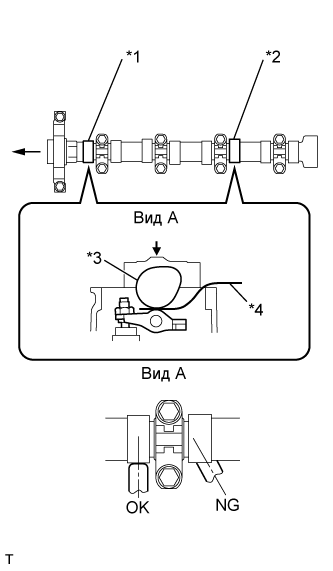
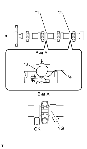
Обозначения на рисунке *1 № 1 на впуске *2 № 3 на выпуске *3 Распредвал *4 Плоский щуп Проверьте зазор в приводе впускного клапана цилиндра № 1 и выпускного клапана цилиндра № 3.
-
Поверните шкив коленчатого вала еще на 180° по часовой стрелке.
-
Щупом измерьте зазор между и распредвалом и рычагом привода клапанов № 1, как показано на рисунке.
Зазор в приводе клапанов (холодный двигатель) 0,11–0,17 мм (0,004–0,007 дюйма) для впуска 0,14–0,20 мм (0,006–0,008 дюйма) для выпуска Note
-
Вставьте плоский щуп в центре поверхности ролика параллельно рычагу привода клапана № 1.
-
Не прилагайте чрезмерного усилия к винту регулировки клапана при использовании регулировочных инструментов во время измерения или регулировки.
Tech Tips
Если зазор не соответствует требованиям, запишите неудовлетворительный результат измерения, а затем отрегулируйте зазор в приводе клапанов.
-
-
-
Обозначения на рисунке *1 № 3 на впуске *2 № 4 на выпуске *3 Распредвал *4 Плоский щуп Проверьте зазоры в приводах впускного клапана цилиндра № 3 и выпускного клапана цилиндра № 4.
-
Поверните шкив коленчатого вала еще на 180° по часовой стрелке.
-
Щупом измерьте зазор между и распредвалом и рычагом привода клапанов № 1, как показано на рисунке.
Зазор в приводе клапанов (холодный двигатель) 0,11–0,17 мм (0,004–0,007 дюйма) для впуска 0,14–0,20 мм (0,006–0,008 дюйма) для выпуска Note
-
Вставьте плоский щуп в центре поверхности ролика параллельно рычагу привода клапана № 1.
-
Не прилагайте чрезмерного усилия к винту регулировки клапана при использовании регулировочных инструментов во время измерения или регулировки.
Tech Tips
Если зазор не соответствует требованиям, запишите неудовлетворительный результат измерения, а затем отрегулируйте зазор в приводе клапанов.
-
-
-
Обозначения на рисунке *1 № 2 на выпуске *2 № 4 на впуске *3 Распредвал *4 Плоский щуп Проверьте зазоры в приводах впускного клапана цилиндра № 2 и впускного клапана цилиндра № 4.
-
Поверните шкив коленчатого вала еще на 180° по часовой стрелке.
-
Щупом измерьте зазоры между и распредвалом и рычагом привода клапанов № 1.
Зазор в приводе клапанов (холодный двигатель) 0,11–0,17 мм (0,004–0,007 дюйма) для впуска 0,14–0,20 мм (0,006–0,008 дюйма) для выпуска Note
-
Вставьте плоский щуп в центре поверхности ролика параллельно рычагу привода клапана № 1.
-
Не прилагайте чрезмерного усилия к винту регулировки клапана при использовании регулировочных инструментов во время измерения или регулировки.
Tech Tips
Если зазор не соответствует требованиям, запишите неудовлетворительный результат измерения, а затем отрегулируйте зазор в приводе клапанов.
-
-
-
-
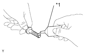
ADJUST VALVE CLEARANCE
-
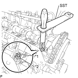
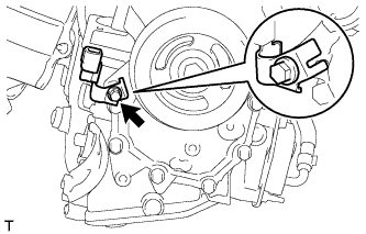
Обозначения на рисунке *1 Регулировочный винт *2 Контргайка С помощью SST и отвертки ослабьте гайку регулировки клапана, удерживая винт регулировки клапана на месте.
- SST
- 09248-56010
-
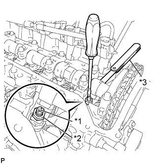
Обозначения на рисунке *1 Регулировочный винт *2 Контргайка *3 Плоский щуп Отрегулируйте зазор в приводе клапанов (на впуске).
-
Вставьте плоский щуп (0,14 мм (0,006 дюйма)) между распредвалом и рычагом привода клапана № 1, и поверните винт регулировки клапана для регулировки.
Зазор в приводе клапанов (холодный двигатель) 0,14 мм (0,006 дюйма) -
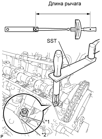
Обозначения на рисунке *1 Регулировочный винт *2 Контргайка С помощью SST и отвертки затяните гайку регулировки клапана, удерживая винт регулировки клапана на месте.
- Torque:
- При использовании SST
- 13 Н*м { 133 кгс*см, 10 фунт-сила-дюймов }
- Без использования SST
- 20 Н*м { 204 кгс*см, 15 фунт-сила-дюймов }
Tech Tips
-
Данное значение крутящего момента получено при использовании динамометрического ключа с длиной рычага 300 мм (11,81 дюйма) и SST с длиной рычага 150 мм (5,91 дюйма) (см. стр. Click here).
-
Данное значение крутящего момента действительно в случае, если SST установлен параллельно динамометрическому ключу.
-
-
Отрегулируйте зазор в приводе клапанов (на выпуске).
Зазор в приводе клапанов (холодный двигатель) 0,17 мм (0,007 дюйма) Tech Tips
Выполните такую же процедуру, что и для регулировки зазора в приводе клапанов со стороны впуска.
-
-
INSTALL CYLINDER HEAD COVER SUB-ASSEMBLY
-
Install the cylinder head gasket onto the cylinder head cover.
-
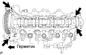
Apply seal packing to the 4 locations shown in the illustration, and then install the cylinder head cover.
Seal packing Toyota Genuine Seal Packing Black, Three Bond 1207B or equivalent Note
-
Remove any oil from the contact surface.
-
Install the cylinder head cover within 3 minutes, and tighten the bolts within 15 minutes of applying the seal packing.
-
-
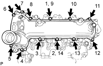
Temporarily tighten the cylinder head cover with the 12 bolts.
-
Fully tighten the 12 bolts, as shown in the illustration.
- Torque:
- 11 N*m { 112 kgf*cm, 8 ft.*lbf }
-
-
INSTALL HARNESS BRACKET (w/o Air Conditioning System)
-
Install the harness bracket with the bolt.
- Torque:
- 13 N*m { 130 kgf*cm, 9 ft.*lbf }
-
-
INSTALL V-RIBBED BELT TENSIONER ASSEMBLY
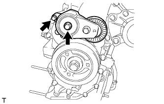
-
Install the V-ribbed belt tensioner with the 2 bolts.
- Torque:
- 24 N*m { 245 kgf*cm, 18 ft.*lbf }
-
-
INSTALL IDLER PULLEY SUB-ASSEMBLY
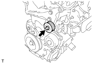
-
Install the idler pulley with the bolt.
- Torque:
- 40 N*m { 408 kgf*cm, 30 ft.*lbf }
-
-
INSTALL VACUUM PUMP ASSEMBLY
-
Install 2 new O-rings to the vacuum pump.
-
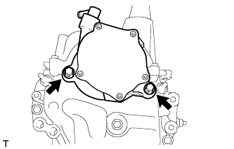
Install the vacuum pump with the 2 bolts.
- Torque:
- 21 N*m { 214 kgf*cm, 15 ft.*lbf }
-
-
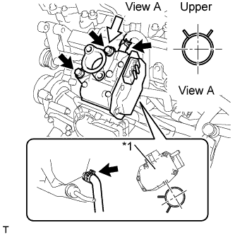
INSTALL CAMSHAFT POSITION SENSOR
-
Install the camshaft position sensor with the bolt.
- Torque:
- 7.0 N*m { 71 kgf*cm, 62 in.*lbf }
-
Install the harness bracket with the bolt.
- Torque:
- 11 N*m { 112 kgf*cm, 8 ft.*lbf }
-
-
INSTALL NO. 2 CYLINDER HEAD COVER
-
Install the No. 2 cylinder head cover.
-
Install the 2 harness brackets with the 2 bolts.
- Torque:
- 11 N*m { 112 kgf*cm, 8 ft.*lbf }
-
-
INSTALL OIL LEVEL DIPSTICK GUIDE
-
Install a new O-ring to the oil level dipstick guide.
-
Install the oil level dipstick guide with the 2 bolts.
- Torque:
- 9.0 N*m { 92 kgf*cm, 80 in.*lbf }
-
-
INSTALL ENGINE OIL LEVEL DIPSTICK
-
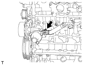
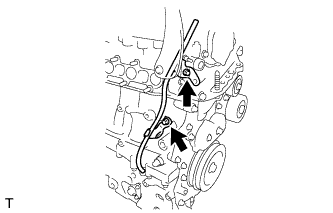
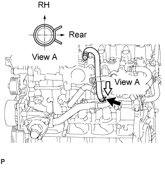
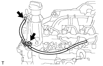
INSTALL WATER BY-PASS PIPE SUB-ASSEMBLY
-
Install a new O-ring to the water by-pass pipe.
-
Install the water by-pass pipe with the 2 bolts, as shown in the illustration.
- Torque:
- 9.0 N*m { 92 kgf*cm, 80 in.*lbf }
-
Connect the water by-pass hose.
-
Connect the oil cooler hose.
-
-
INSTALL NO. 4 WATER BY-PASS HOSE
-
Install the No. 4 water by-pass hose.
-
-
INSTALL NO. 2 OIL COOLER HOSE
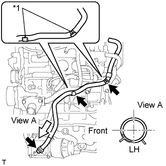
Text in Illustration *1 Paint Mark
-
Install the No. 2 oil cooler hose.
Note
Align the oil cooler hose paint mark with the clamp center.
-
Text in Illustration *1 Paint Mark Install the hose clamp.
Note
Align the oil cooler hose paint mark with the clamp center.
-
-
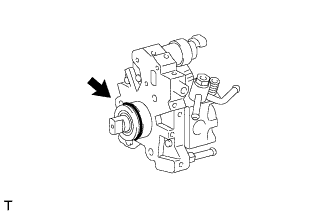
INSTALL SUPPLY PUMP DRIVE COUPLING
-
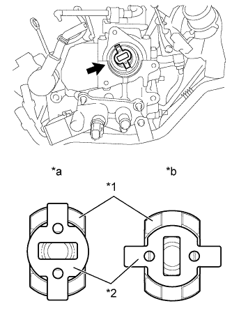
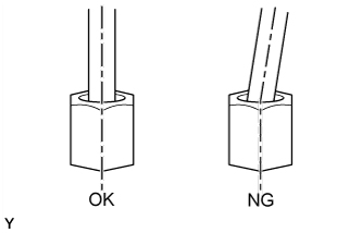
Text in Illustration *1 Camshaft *2 Supply Pump Drive Coupling *a Correct *b Incorrect Install the supply pump drive coupling into the camshaft.
Note
Install the supply pump drive coupling in the correct direction.
-
-
TEMPORARILY TIGHTEN SUPPLY PUMP ASSEMBLY
Note
When installing, clean the seal surfaces of the fuel inlet pipe, supply pump and common rail.
-
Apply a light coat of engine oil to a new O-ring.
-
Install the O-ring onto the supply pump.
-
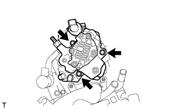
Temporarily tighten the supply pump with the 3 bolts.
-
-
INSTALL FUEL INLET PIPE SUB-ASSEMBLY
Note
-
When replacing the supply pump. the fuel inlet pipe must also be replaced.
-
Replace the fuel inlet pipe with a new one when the fuel inlet pipe has been removed and reinstalled more than 5 times.
-
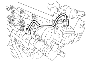
Temporarily tighten the fuel inlet pipe onto the supply pump and common rail.
Note
Install the pipe and union nut vertically. not at a tilt.
-
Fully tighten the supply pump with the 3 bolts.
- Torque:
- 21 N*m { 214 kgf*cm, 15 ft.*lbf }
-
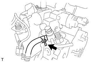
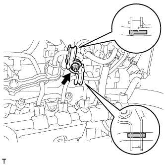
Using a union nut wrench (17 mm), tighten the fuel inlet pipe union nut on the common rail side.
- Torque:
- 28 N*m { 286 kgf*cm, 20 ft.*lbf }
Note
Use the formula to calculate special torque values for situations where a union nut wrench is combined with a torque wrench Click here.
-
Using a wrench (17 mm), hold the supply pump nut, and using a union nut wrench (17 mm), tighten the fuel inlet pipe union nut on the supply pump side.
- Torque:
- 28 N*m { 286 kgf*cm, 20 ft.*lbf }
Note
Use the formula to calculate special torque values for situations where a union nut wrench is combined with a torque wrench Click here.
-
-
CONNECT NO. 2 FUEL HOSE
-
Connect the No. 2 fuel hose.
-
-
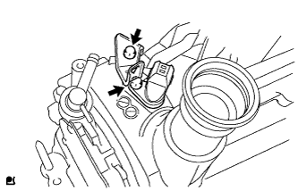
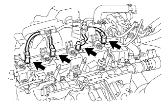
INSTALL NOZZLE LEAKAGE PIPE ASSEMBLY
-
Install the nozzle leakage pipe into each injector.
-
Make sure the lock bush is at top position.
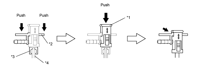
Text in Illustration *1 Lock Bush *2 Return Plug *3 Rest Arm *4 Injector -
Insert the rest arm into the injector and push both sides of the return plug until the rest arm engages with the injector, as shown in the illustration.
Tech Tips
Push the nozzle leakage pipe until it makes a click sound.
-
Push the lock bush until the it fits with the return plug, as shown in the illustration.
-
-
Connect the nozzle leakage pipe and install new retainer spring onto the supply pump.
-
-
INSTALL NOZZLE LEAKAGE PIPE SET CLAMP
-
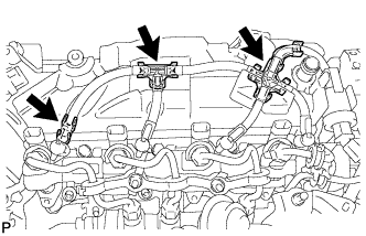
Install the 3 nozzle leakage pipe set clamps.
-
-
INSTALL NO. 2 INJECTION PIPE CLAMP
-
Install both sides of the No. 2 injection pipe clamp with the nut as shown in the illustration.
- Torque:
- 9.0 N*m { 92 kgf*cm, 80 in.*lbf }
-
-
INSTALL INTAKE AIR CONNECTOR WITH DIESEL THROTTLE BODY
-
Install the new gasket to the cylinder head.
-
Install the intake air connector with the diesel throttle body with the 2 bolts and 2 nuts.
- Torque:
- 23 N*m { 235 kgf*cm, 17 ft.*lbf }
-
-
INSTALL ELECTRIC EGR CONTROL VALVE ASSEMBLY
-
Install a new gasket.
-
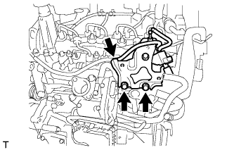
Text in Illustration *1 Adhesive Apply adhesive to the 2 bolts.
Adhesive Toyota Genuine Adhesive 1324, Three Bond 1324 or equivalent. -
Text in Illustration *1 EGR Control Valve Install the electric EGR control valve with the 2 bolts.
- Torque:
- 23 N*m { 235 kgf*cm, 17 ft.*lbf }
-
Connect the No. 3 water by-pass hose.
-
Connect the No. 4 water by-pass hose.
-
-
INSTALL HARNESS BRACKET
-
Install the harness bracket with the bolt.
- Torque:
- 10 N*m { 102 kgf*cm, 7 ft.*lbf }
-
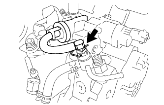
Connect the vacuum hose to the vacuum pump.
-
-
INSTALL NO. 1 EGR COOLER BRACKET
-
Install the No. 1 EGR cooler bracket with the 2 bolts.
- Torque:
- 23 N*m { 235 kgf*cm, 17 ft.*lbf }
-
Connect the vacuum hose.
-
-
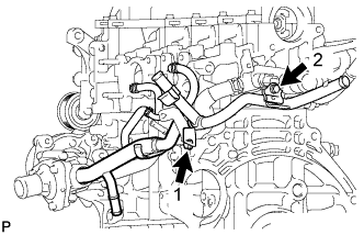
INSTALL EGR WITH COOLER PIPE ASSEMBLY
-
Install 2 new gaskets.
-
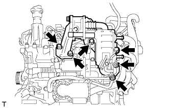
Install the EGR with cooler pipe assembly with the 4 bolts and 2 nuts.
- Torque:
- 23 N*m { 235 kgf*cm, 17 ft.*lbf }
-
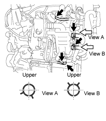
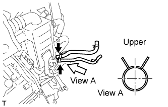
Connect the No. 2 water by-pass hose.
-
Connect the No. 2 oil cooler hose.
-
Connect the 2 vacuum hoses and No. 1 oil hose.
-
Connect the No. 1 vacuum transmitting hose.
-
Connect the vacuum transmitting hose.
-
-
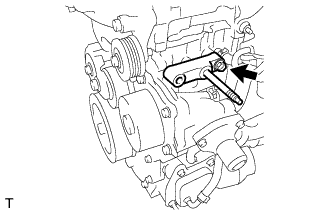
INSTALL GENERATOR BRACKET
-
Install the No. 1 generator bracket with the bolt.
- Torque:
- 40 N*m { 407 kgf*cm, 30 ft.*lbf }
-
-
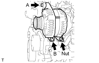
INSTALL GENERATOR ASSEMBLY
-
Install the generator with the 2 bolts and nut.
- Torque:
- Bolt A
- 21 N*m { 214 kgf*cm, 15 ft.*lbf }
- Bolt B, Nut
- 54 N*m { 551 kgf*cm, 40 ft.*lbf }
-
-
INSTALL ENGINE ASSEMBLY
-
Install the engine assembly Click here.
-