БЛОК ДВИГАТЕЛЯ ПОВТОРНАЯ СБОРКА

-
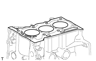
INSTALL CYLINDER HEAD GASKET
-
Place a new cylinder head gasket on the cylinder block sub-assembly.
-
-
INSTALL CYLINDER HEAD SUB-ASSEMBLY
Note
Place the cylinder head gently in order not to damage the gasket.
-
Place the cylinder head on the cylinder block sub-assembly.
-
Install the 8 plate washers to the cylinder head sub-assembly.
Note
Do not drop the washers into the cylinder head.
-
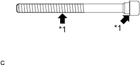
Text in Illustration *1 Apply Engine Oil. Apply engine oil to each bolt thread and seating surface.
-
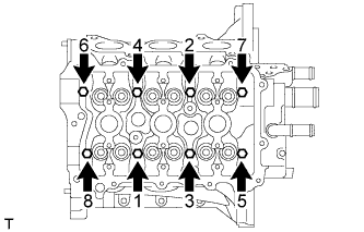
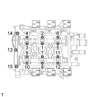
Using several passes, uniformly install and tighten the 8 cylinder head bolts with an 8 mm bi-hexagon wrench in the order shown in the illustration.
- Torque:
- 32 N*m { 326 kgf*cm, 24 ft.*lbf }
-
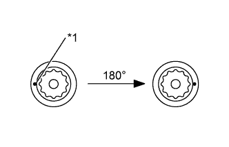
Mark the front of each cylinder head bolt with paint.
-
Retighten the cylinder head bolts by additional 180° as shown in the illustration.
Text in Illustration *1 Paint Mark -
Check that the paint mark are now 180° from the front.
-
-
INSTALL VALVE LIFTER
-
Apply engine oil to the circumference of the valve lifters.
-
Install the valve lifters straight into the lifter holes.
Note
Check that the valve lifters turn smoothly after installing them.
-
-
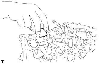
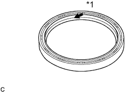
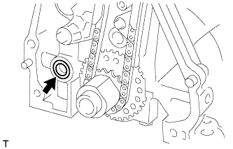
INSTALL ENGINE REAR OIL SEAL
Text in Illustration *1 Apply Engine Oil.
-
Apply engine oil to the lip of a new oil seal.
-
Using SST, tap the oil seal straight in.

Text in Illustration *1 Rear Oil Seal Retainer - - - SST
- 09223-15020
- 09950-70010 ( 09951-07200 )
Correct oil seal position Protrusion from rear oil seal retainer edge 0.5 mm (0.020 in.) or less Installation depth from rear oil seal retainer edge 1.0 mm (0.039 in.) or less
-
-
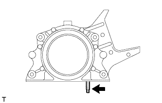
INSTALL ENGINE REAR OIL SEAL RETAINER
-
Install the stud bolt.
-
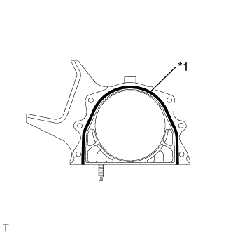
Text in Illustration *1 Seal Packing Apply a continuous bead of seal packing (Diameter 3 to 4 mm (0.12 to 0.16 in.)) as shown in the illustration.
Seal packing Toyota Genuine Seal Packing Black, Three Bond 1207B or equivalent -
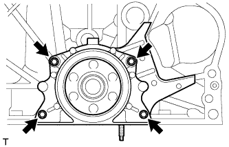
Install the oil seal retainer with the 4 bolts.
- Torque:
- 10 N*m { 102 kgf*cm, 7 ft.*lbf }
Note
-
Install the oil seal retainer within 3 minutes and tighten the bolts within 15 minutes after applying seal packing.
-
Do not add engine oil for at least 2 hours after installation.
-
Do not start the engine for at least 2 hours after installation.
-
-
INSTALL CAMSHAFTS
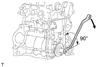
-
Before installing the camshaft, turn the crankshaft approximately 90° in the engine revolution direction from the point where the No. 1 piston is set at the TDC/ compression so that the lifted valve and piston do not touch each other.
-
Text in Illustration *1 Apply Engine Oil. Apply engine oil to the contact areas of the cam and journal of the camshaft and No. 2 camshaft.
-
Text in Illustration *1 No. 1 Camshaft *2 No. 2 Camshaft *3 No. 3 Cylinder *4 No. 1 Cylinder *5 No. 2 Cylinder Install the camshafts as shown in the illustration.
-
Set the No. 1 camshaft bearing cap and No. 2 camshaft bearing caps and tighten the bolts in the order shown in the illustration.
- Torque:
- No. 1 camshaft bearing cap
- 15 N*m { 153 kgf*cm, 11 ft.*lbf }
- No. 2 camshaft bearing cap
- 13 N*m { 128 kgf*cm, 9 ft.*lbf }
Note
-
Install the bearing caps with the front marks facing the engine front.
-
Install the bolts in the correct positions by referring to the numbers inscribed on the bolts and the table below.
Installation Position of No. 2 Camshaft Bearing Cap Installation position Inscribed No. Intake No. 1 cylinder I2 Intake No. 2 cylinder I3 Intake No. 3 cylinder I4 Exhaust No. 1 cylinder E2 Exhaust No. 2 cylinder E3 Exhaust No. 3 cylinder E4
-
-
INSTALL CAMSHAFT TIMING GEAR OR SPROCKET
-
Insert the camshaft timing gear or sprocket so that the knock pin on the No. 2 camshaft end fits into the groove.
-
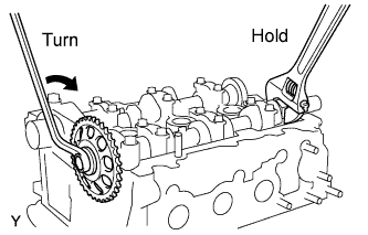
While holding the hexagonal portion of the No. 2 camshaft, tighten the bolts to install the camshaft timing gear or sprocket.
- Torque:
- 47 N*m { 479 kgf*cm, 35 ft.*lbf }
-
-
INSTALL CAMSHAFT TIMING SPROCKET ASSEMBLY
-
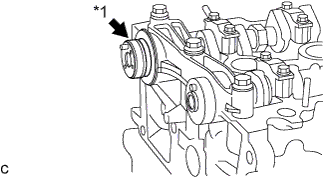
Apply engine oil to the camshaft timing sprocket installation portion of the camshaft.
Text in Illustration *1 Apply Engine Oil. -
Insert the knock pin on the camshaft end into the knock hole in the camshaft timing sprocket.
Note
-
Slightly turn the sprocket to make sure that the knock pin is securely installed after inserting the knock pin.
-
The end surface of the sprocket may be damaged if the sprocket is turned with excessive force when the knock pin is not inserted.
-
-
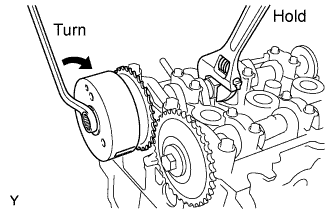
While holding the hexagonal portion of the camshaft, tighten the bolts to install the camshaft timing sprocket.
- Torque:
- 47 N*m { 479 kgf*cm, 35 ft.*lbf }
-
-
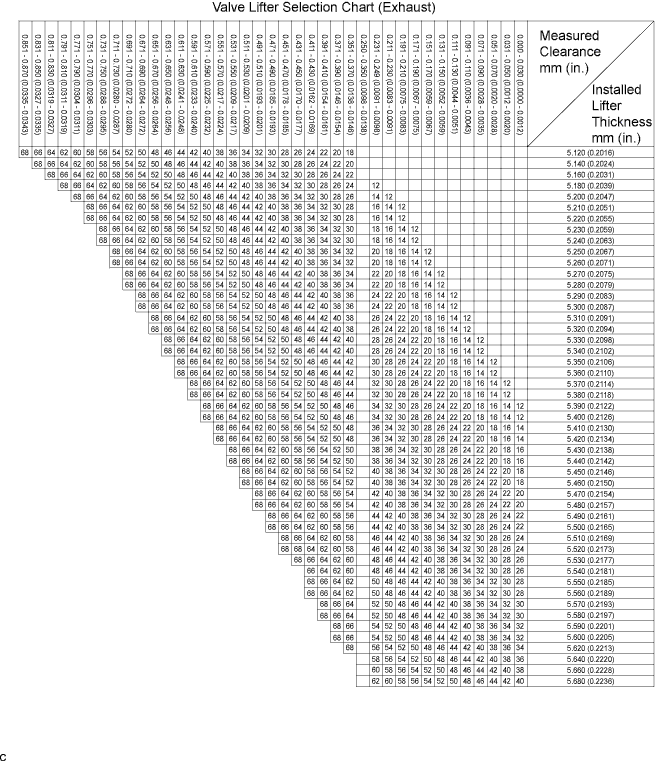
INSPECT VALVE CLEARANCE
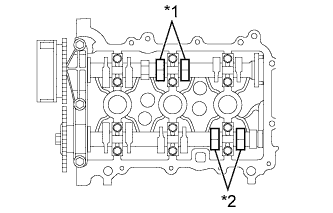
Text in Illustration *1 Intake Side *2 Exhaust Side
-
Check only the valves indicated.
-
Using a feeler gauge, measure the clearance between the valve lifter and camshaft.
Valve clearance (Cold) Intake side 0.145 to 0.235 mm (0.00571 to 0.00925 in.) Exhaust side 0.275 to 0.365 mm (0.01083 to 0.01437 in.) Tech Tips
Insert the feeler gauge from the spark plug side (center).
-
Record any out-of-specification valve clearance measurements. They will be used later to determine the required replacement valve lifters.
-
-
Turn the crankshaft 1 revolution (360°).
-
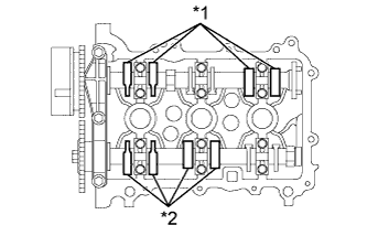
Text in Illustration *1 Intake Side *2 Exhaust Side Check only the valves indicated.
-
Using a feeler gauge, measure the clearance between the valve lifter and camshaft.
Valve clearance (Cold) Intake side 0.145 to 0.235 mm (0.00571 to 0.00925 in.) Exhaust side 0.275 to 0.365 mm (0.01083 to 0.01437 in.) Tech Tips
Insert the feeler gauge from the spark plug side (center).
-
Record any out-of-specification valve clearance measurements. They will be used later to determine the required replacement valve lifters.
-
-
-
ADJUST VALVE CLEARANCE
-
Remove the No. 1 and No. 2 camshafts Click here.
-
Remove the valve lifters Click here.
-
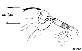
Using a micrometer, measure the thickness of the removed valve lifters.
-
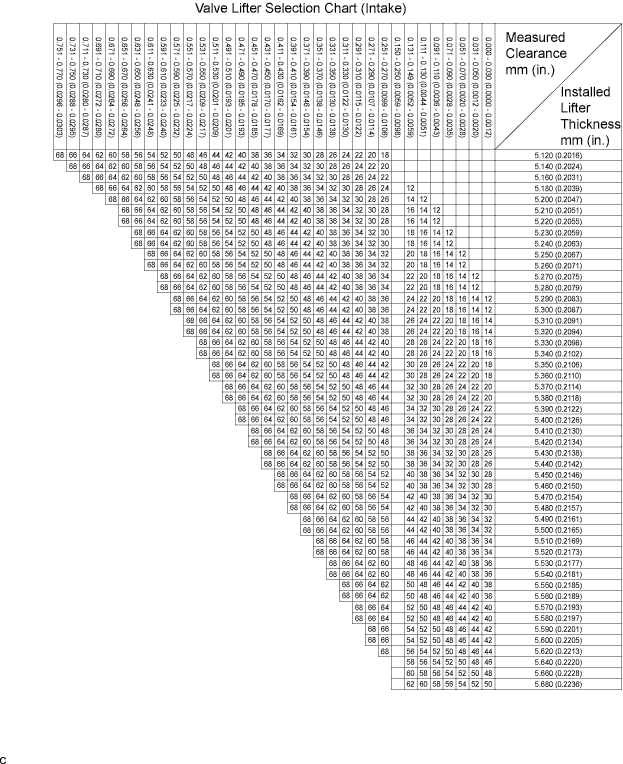
Calculate the thickness of a new lifter so that the valve clearance comes within the specified value.
A Thickness of new lifter B Thickness of used lifter C Measured valve clearance Valve clearance Intake A = B + (C - 0.18 mm (0.0071 in.)) Exhaust A = B + (C - 0.31 mm (0.0122 in.)) Tech Tips
-
Select a new lifter with a thickness as close to the calculated values as possible.
-
Lifters are available in 29 sizes in increments of 0.020 mm (0.0008 in.), from 5.12 mm (0.2016 in.) to 5.68 mm (0.2236 in.).
-
Refer to the New Lifter Thickness Table on the next 2 pages.
-
-
Install the valve lifters Click here.
-
Install the No. 1 and No. 2 camshafts Click here.
Tech Tips
New Lifter Thickness mm (in.) Lifter No. Thickness Lifter No. Thickness Lifter No. Thickness 12 5.12 (0.2016) 32 5.32 (0.2094) 52 5.52 (0.2173) 14 5.14 (0.2024) 34 5.34 (0.2102) 54 5.54 (0.2181) 16 5.16 (0.2031) 36 5.36 (0.2110) 56 5.56 (0.2189) 18 5.18 (0.2039) 38 5.38 (0.2118) 58 5.58 (0.2197) 20 5.20 (0.2047) 40 5.40 (0.2126) 60 5.60 (0.2205) 22 5.22 (0.2055) 42 5.42 (0.2134) 62 5.62 (0.2213) 24 5.24 (0.2063) 44 5.44 (0.2142) 64 5.64 (0.2220) 26 5.26 (0.2071) 46 5.46 (0.2150) 66 5.66 (0.2228) 28 5.28 (0.2079) 48 5.48 (0.2157) 68 5.68 (0.2236) 30 5.30 (0.2087) 50 5.50 (0.2165) - -
-
-
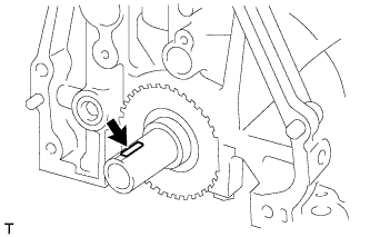
INSTALL CRANKSHAFT STRAIGHT PIN
-
Install the crankshaft straight pin into the crankshaft groove.
-
-
INSTALL CRANKSHAFT TIMING GEAR OR SPROCKET
-
Align the groove of the crankshaft timing sprocket with the key of the crankshaft and install the crankshaft timing sprocket.
-
-
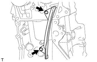
INSTALL TIMING CHAIN GUIDE
-
Install the timing chain guide with the 2 bolts.
- Torque:
- 9.0 N*m { 92 kgf*cm, 80 in.*lbf }
-
-
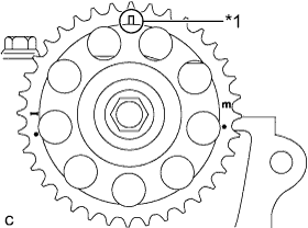
INSTALL CHAIN SUB-ASSEMBLY
Text in Illustration *1 Yellow Mark Plate *2 Timing Mark
-
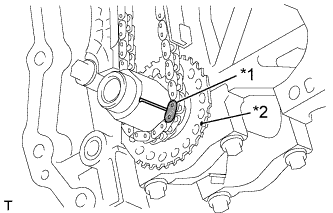
Align the yellow mark plate with the timing mark of the crankshaft timing sprocket and install the timing chain, as shown in the illustration.
-
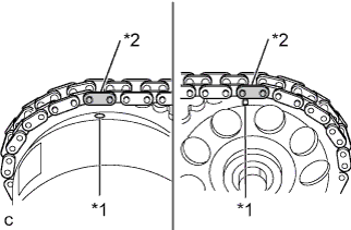
Text in Illustration *1 Timing Mark *2 Orange Mark Plate Align the 2 orange mark plates with the timing marks of the camshaft timing sprockets and install the timing chain, as shown in the illustration.
-
-
INSTALL TIMING CHAIN TENSION ARM

-
Install the timing chain tension arm with the bolt.
- Torque:
- 19 N*m { 194 kgf*cm, 14 ft.*lbf }
-
-
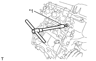
INSTALL NO. 1 CHAIN TENSIONER ASSEMBLY
-
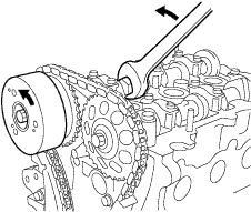
Slightly turn the hexagonal portion of the camshaft (intake side) counterclockwise to leave some slack on the chain of the timing chain tensioner side.
-
Install the No. 1 chain tensioner assembly with the 2 bolts.
- Torque:
- 8.0 N*m { 82 kgf*cm, 71 in.*lbf }
-
Remove the hexagon wrench, turn the crankshaft 2 complete revolutions and operate the chain tension assembly.
Text in Illustration *1 Hexagon Wrench -
Text in Illustration *1 Timing Mark Make sure that the timing mark of the sprocket camshaft timing is at the top with the timing chain tensed (set No. 1 piston to the TDC/ compression).
-
-
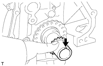
INSTALL OIL PUMP GASKET
-
Install a new oil pump gasket onto the cylinder block.
-
-
INSTALL VENTILATION CASE SUB-ASSEMBLY
-
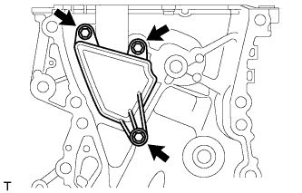
Install the ventilation case sub-assembly with the 3 bolts.
- Torque:
- 10 N*m { 102 kgf*cm, 7 ft.*lbf }
-
-
INSTALL TIMING CHAIN OR BELT COVER OIL SEAL
-
Apply engine oil to the lip of a new oil seal.
Text in Illustration *1 Apply Engine Oil. -
Using SST, tap the oil seal straight in.
- SST
- 09950-60010 ( 09951-00500, 09952-06010 )
- 09950-70010 ( 09951-07200 )
Correct oil seal position Protrusion from chain cover edge 0.5 mm (0.020 in.) or less Installation depth from chain cover edge 1.0 mm (0.039 in.) or less
-
-
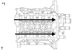
INSTALL TIMING CHAIN OR BELT COVER SUB-ASSEMBLY
-
Remove any oil packing (FIPG) material and be careful not to drop any oil on the contact surfaces of the timing chain cover sub-assembly, cylinder head, and cylinder block.
-
Apply seal packing as shown in the illustration.
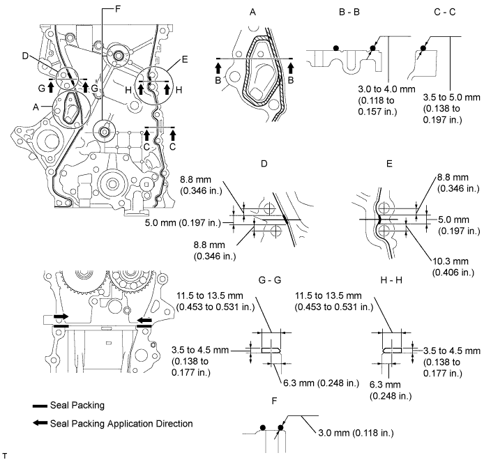
Seal packing Toyota Genuine Seal Packing Black, Three Bond 1207B or equivalent Note
-
Install the timing chain cover sub-assembly within 3 minutes and tighten the bolts within 15 minutes after applying seal packing.
-
Do not add engine oil for at least 2 hours after installation.
-
Do not start the engine for at least 2 hours after installation.
-
-
Temporarily install the timing chain cover sub-assembly with the 12 bolts.
Bolt Length Item Length Bolt A 80 mm (3.15 in.) Bolt B 40 mm (1.57 in.) Bolt C 45 mm (1.77 in.) Bolt D 70 mm (2.78 in.) Bolt E 45 mm (1.77 in.) -
Install the new gasket to the timing chain cover sub-assembly.
-
Temporarily install the oil filter bracket with the 2 bolts.
Bolt Length Item Length Bolt A 20 mm (0.79 in.) Bolt B 119 mm (4.69 in.) -
Install the new gasket to the timing chain cover sub-assembly.
-
Temporarily install the water pump assembly with 5 bolts.
Bolt Length Item Length Bolt A 55 mm (2.17 in.) Bolt B 20 mm (0.79 in.) -
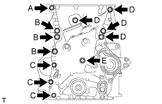
Fully tighten the timing chain cover sub-assembly with the 19 bolts as shown in the illustration.
- Torque:
- 24 N*m { 245 kgf*cm, 18 ft.*lbf, (Bolt A, C, E, F, G) }
- 40 N*m { 408 kgf*cm, 30 ft.*lbf, (Bolt B, D) }
- 10 N*m { 102 kgf*cm, 7 ft.*lbf, (Bolt H) }
Note
-
Install the chain cover within 3 minutes and tighten the bolts within 15 minutes after applying seal packing.
-
Do not add engine oil for at least 2 hours after installation.
-
Do not start the engine for at least 2 hours after installation.
Bolt Length Item Length Bolt A 80 mm (3.15 in.) Bolt B 40 mm (1.57 in.) Bolt C 45 mm (1.77 in.) Bolt D 70 mm (2.78 in.) Bolt E 55 mm (2.17 in.) Bolt F 20 mm (0.79 in.) Bolt G 119 mm (4.69 in.) Bolt H 45 mm (1.77 in.) -
Remove excess seal packing.
-
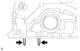
Install the 2 stud bolts.
-
-
INSTALL TIMING GEAR COVER TIGHT PLUG
Text in Illustration *1 Seal Packing
-
Clean the timing gear cover tight plug and installation surface of the timing chain cover.
-
Apply a light coat of the seal packing black to the timing gear cover tight plug.
Seal packing Toyota Genuine Seal Packing Black, Three Bond 1207B or equivalent Note
-
Install the timing gear tight plug within 3 minutes and tighten the bolts within 15 minutes after applying seal packing.
-
Do not add engine oil for at least 2 hours after installation.
-
Do not start the engine for at least 2 hours after installation.
-
-
Text in Illustration *1 8 mm Socket Hexagon Wrench Using an 8 mm socket hexagon wrench, install the timing gear cover tight plug onto the timing chain cover.
- Torque:
- 10 N*m { 102 kgf*cm, 7 ft.*lbf }
-
-
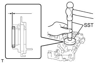
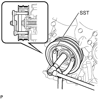
INSTALL CRANKSHAFT PULLEY
-
Align the pulley set key with the key groove of the pulley.
-
Using SST, hold the pulley in place and tighten the bolt.
- SST
- 09960-10010 ( 09962-01000, 09963-01000 )
- Torque:
- 180 N*m { 1836 kgf*cm, 133 ft.*lbf }
-
-
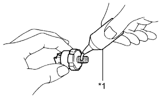
INSTALL OIL FILTER SUB-ASSEMBLY
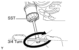
-
Check and clean the oil filter installation surface.
-
Apply clean engine oil to the gasket of a new oil filter.
-
Gently screw the oil filter into place, and then tighten it until the gasket comes into contact with the seat.
-
Using SST, tighten it an additional 3/4 turn.
- SST
- 09228-06501
-
-
INSTALL WATER INLET
-
Install the water inlet with 2 nuts.
- Torque:
- 10 N*m { 102 kgf*cm, 7 ft.*lbf }
-
-
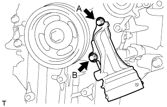
INSTALL NO. 1 WATER BY-PASS PIPE
-
Install a new gasket to the No. 1 water by-pass pipe.
-
Install a new gasket to the cylinder head.
-
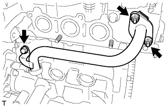
Temporarily tighten the bolt and install the 2 nuts.
- Torque:
- 24 N*m { 245 kgf*cm, 18 ft.*lbf }
-
Fully tighten the bolt.
- Torque:
- 24 N*m { 245 kgf*cm, 18 ft.*lbf }
-
-
INSTALL WATER VALVE
-
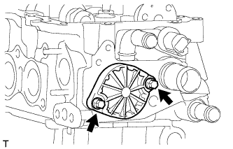
Install a new gasket to the water valve.
-
Install the water valve with the 2 bolts.
- Torque:
- 7.0 N*m { 71 kgf*cm, 62 in.*lbf }
-
-
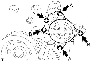
INSTALL OIL STRAINER SUB-ASSEMBLY
-
Install a new oil strainer gasket onto the oil strainer.
-
Install the oil strainer with the 2 bolts.
- Torque:
- 8.5 N*m { 87 kgf*cm, 75 in.*lbf }
-
-
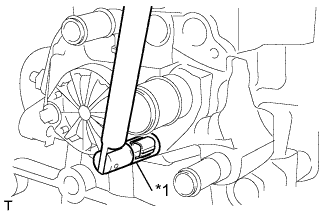
INSTALL OIL PAN SUB-ASSEMBLY
-
Remove any grease from the installation surfaces of the cylinder block sub-assembly and oil pan sub-assembly.
-
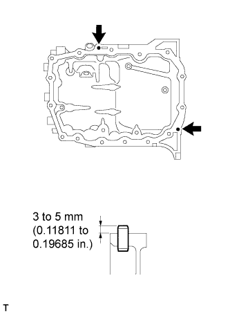
Using a plastic hammer, tap into the straight pin, as shown in the illustration.
Standard protrusion 3 to 5 mm (0.11811 to 0.19685 in.) -
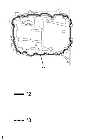
Text in Illustration *1 Seal Packing *2 Contact surface between timing chain cover and cylinder block *3 Contact surface between oil seal retainer and cylinder block Apply seal packing to the oil pan sub-assembly and install it onto the cylinder block assembly.
Seal packing Toyota Genuine Seal Packing Black, Three Bond 1207B or equivalent. Note
-
Start and finish applying the seal packing on the seal surface with the cylinder block sub-assembly.
-
Apply seal packing to the contact surfaces between the timing chain cover and cylinder block, and between the oil seal retainer and cylinder block.
-
Install the oil pan sub-assembly within 3 minutes and tighten the bolts within 15 minutes of applying seal packing.
-
-
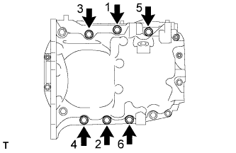
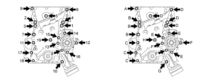
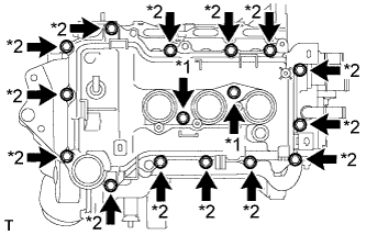
Tighten the specified 6 bolts in the order shown in the illustration.
- Torque:
- 24 N*m { 245 kgf*cm, 18 ft.*lbf }
-
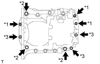
Text in Illustration *1 Nut *2 Bolt A *3 Bolt B Tighten the 6 bolts and 3 nuts.
- Torque:
- Nut and Bolt B
- 10 N*m { 102 kgf*cm, 7 ft.*lbf }
- Bolt A
- 24 N*m { 245 kgf*cm, 18 ft.*lbf }
-
-
INSTALL OIL FILTER BRACKET STAY
-
Install the oil filter bracket stay with 2 bolts.
- Torque:
- 24 N*m { 245 kgf*cm, 18 ft.*lbf }
-
-
INSTALL OIL PAN DRAIN PLUG
-
Install the engine oil drain plug with a new gasket.
- Torque:
- 30 N*m { 301 kgf*cm, 22 ft.*lbf }
-
-
INSPECT VALVE CLEARANCE
-
ADJUST VALVE CLEARANCE
-
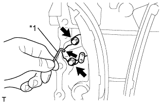
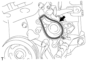
INSTALL VENTILATION VALVE SUB-ASSEMBLY
Text in Illustration *1 Grommet *2 Ventilation Valve Sub-Assembly
-
Install the grommet, as shown in the illustration.
-
Install the ventilation valve sub-assembly.
-
-
INSTALL CYLINDER HEAD COVER SUB-ASSEMBLY
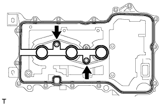
-
Fit the cylinder head cover gasket into the groove on the cylinder head cover and onto the center bosses.
Note
Insert the gasket securely until it completely fits into the bosses.
-
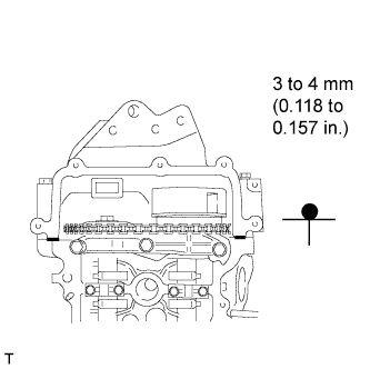
Apply a continuous bead of seal packing (diameter: 3 to 4 mm (0.118 to 0.157 in.)) to the contact surface between the cylinder head assembly and timing chain cover assembly, as shown in the illustration.
Seal packing Toyota Genuine Seal Packing Black, Three Bond 1207B or equivalent Note
Install the cylinder head cover within 3 minutes and tighten the bolts and nuts within 15 minutes of applying seal packing.
-
Text in Illustration *1 Bolt A *2 Bolt B Tighten the bolts A, and then the bolts B.
- Torque:
- 7.7 N*m { 77 kgf*cm, 68 in.*lbf }
-
Check once more that the bolts A meet the specified torque.
- Torque:
- 7.7 N*m { 77 kgf*cm, 68 in.*lbf }
-
-
INSTALL OIL FILLER CAP SUB-ASSEMBLY
-
Install a new gasket onto the oil filler cap.
-
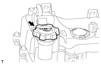
Install the oil filler cap.
-
-
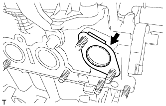
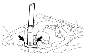
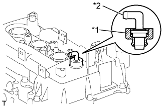
INSTALL OIL CONTROL VALVE FILTER
Text in Illustration *1 Oil Control Valve Filter *2 Gasket *3 Head Taper Screw Plug
-
Install the oil control valve filter onto the head taper screw plug.
-
Text in Illustration *1 8 mm Hexagon Wrench Install a new gasket and install the oil control valve filter using an 8 mm hexagon wrench.
- Torque:
- 25 N*m { 250 kgf*cm, 18 ft.*lbf }
-
-
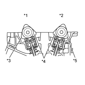
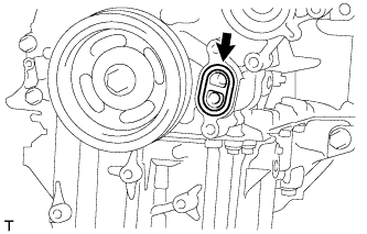
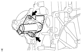
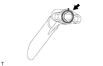
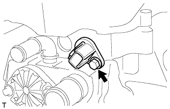
INSTALL KNOCK CONTROL SENSOR
-
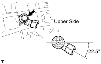
Install the knock control sensor with the bolt.
- Torque:
- 20 N*m { 204 kgf*cm, 15 ft.*lbf }
Note
Position the knock control sensor as shown in the illustration.
-
-
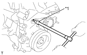
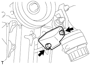
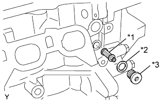
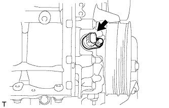
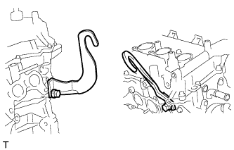
INSTALL ENGINE OIL PRESSURE SWITCH ASSEMBLY
-
Text in Illustration *1 Adhesive Apply adhesive to 2 or 3 threads of the oil pressure switch.
Adhesive Toyota Genuine Adhesive 1324, Three Bond 1324 or equivalent. -
Text in Illustration *1 24 mm Deep Socket Wrench Using a 24 mm deep socket wrench, install the oil pressure switch assembly.
- Torque:
- 10 N*m { 102 kgf*cm, 7 ft.*lbf }
Note
Do not start the engine for at least 1 hour after installation.
-
-
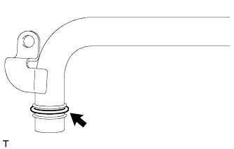
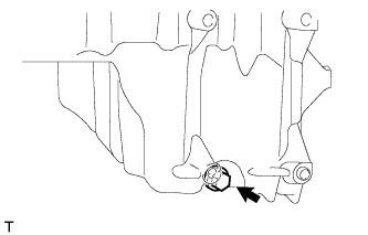
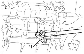
INSTALL CRANKSHAFT POSITION SENSOR
Note
-
Do not use parts that have been dropped or hit.
-
Make sure that the O-ring is not damaged before installing it.
-
Apply a light coat of engine oil to the O-ring.
-
Install the crankshaft position sensor with the bolt.
- Torque:
- 7.5 N*m { 77 kgf*cm, 66 in.*lbf }
-
-
INSTALL CAMSHAFT TIMING OIL CONTROL VALVE ASSEMBLY
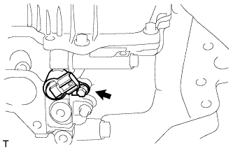
Note
Make sure that the O-ring is not damaged before installing it.
-
Apply a light coat of engine oil to the O-ring.
-
Install the camshaft timing oil control valve with the bolt.
- Torque:
- 10 N*m { 102 kgf*cm, 7 ft.*lbf }
-
-
INSTALL ENGINE COOLANT TEMPERATURE SENSOR
Text in Illustration *1 19 mm Deep Socket Wrench Note
Do not use parts that have been dropped or hit.
-
Install a new gasket onto the engine coolant temperature sensor.
-
Using a 19 mm deep socket wrench, install the engine coolant temperature sensor.
- Torque:
- 20 N*m { 200 kgf*cm, 14 ft.*lbf }
-
-
INSTALL CAMSHAFT POSITION SENSOR
Note
-
Do not use parts that have been dropped or hit.
-
Make sure that the O-ring is not damaged before installing it.
-
Apply a light coat of engine oil to the O-ring.
-
Install the camshaft position sensor with the bolt.
- Torque:
- 7.5 N*m { 77 kgf*cm, 66 in.*lbf }
-
-
INSTALL SPARK PLUG
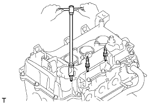
Note
Do not use parts that have been dropped or hit.
-
Install the 3 spark plugs.
- Torque:
- 25 N*m { 255 kgf*cm, 18 ft.*lbf }
-
-
INSTALL ENGINE HANGERS
-
Install the 2 engine hangers with the 2 bolts.
- Torque:
- 28 N*m { 285 kgf*cm, 21 ft.*lbf }
-