БЛОК ДВИГАТЕЛЯ РАЗБОРКА

CAUTION:
-
Prolonged and repeated contact with engine oil will result in the removal of natural oils from the skin, leading to dryness, irritation and dermatitis, used engine oil contains potentially harmful contaminants which may cause skin cancer.
-
Take precautions when replacing engine oil to minimize the risk of your skin making contract with used engine oil. Wear protective clothing and gloves that cannot be penetrated by oil. Wash skin with soap and water, or use water-less hand cleaner, to remove any used engine oil thoroughly. Do not use gasoline, thinner, or solvents.
-
Dispose of used oil and used oil filters at designated disposal sites in order to preserve the environment.
-
REMOVE ENGINE HANGERS
-
Remove the 2 bolts and the 2 engine hangers.
-
-
REMOVE SPARK PLUG
-
Remove the 3 spark plugs.
-
-
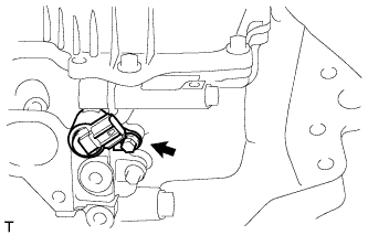
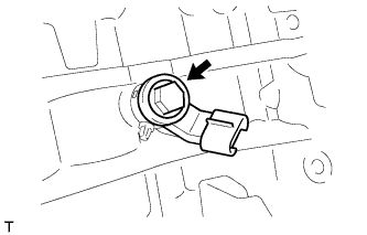
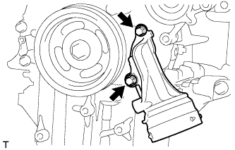
REMOVE CAMSHAFT POSITION SENSOR
-
Remove the bolt and the camshaft position sensor.
-
-
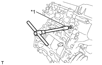
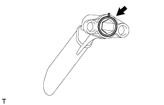
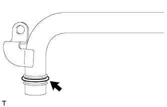
REMOVE ENGINE COOLANT TEMPERATURE SENSOR
Text in Illustration *1 19 mm Deep Socket Wrench
-
Using a 19 mm deep socket wrench, remove the engine coolant temperature sensor.
-
-
REMOVE CAMSHAFT TIMING OIL CONTROL VALVE ASSEMBLY
-
Remove the bolt and the camshaft timing oil control valve.
-
-
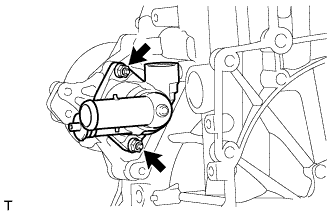
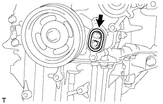
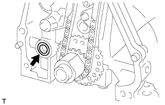
REMOVE CRANKSHAFT POSITION SENSOR
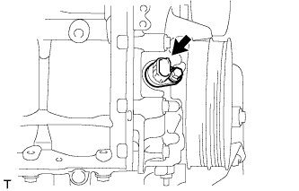
-
Remove the bolt and the crankshaft position sensor.
-
-
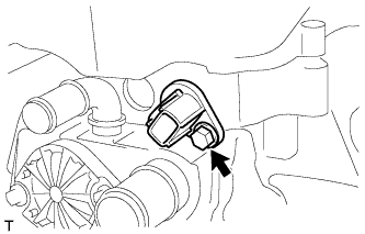
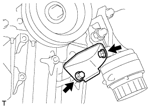
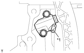
REMOVE ENGINE OIL PRESSURE SWITCH ASSEMBLY
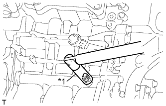
Text in Illustration *1 24 mm Deep Socket Wrench
-
Using a 24 mm deep socket wrench, remove the engine oil pressure switch assembly.
-
-
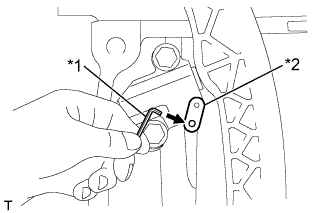
REMOVE KNOCK CONTROL SENSOR
-
Remove the bolt and the knock control sensor.
-
-
REMOVE OIL CONTROL VALVE FILTER
-
Text in Illustration *1 8 mm Socket Hexagon Wrench Using a 8 mm socket hexagon wrench, remove the head taper screw plug.
-
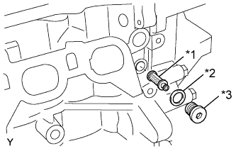
Text in Illustration *1 Oil Control Valve Filter *2 Gasket *3 Head Taper Screw Plug Remove the oil control valve filter and gasket.
-
-
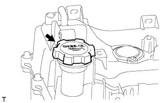
REMOVE OIL FILLER CAP SUB-ASSEMBLY
-
Remove the oil filler cap.
-
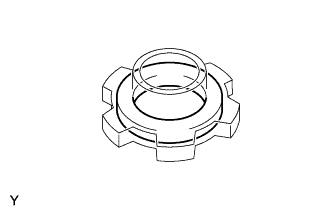
Using a screwdriver, remove the gasket from the oil filler cap.
-
-
REMOVE CYLINDER HEAD COVER SUB-ASSEMBLY
-
Remove the 16 bolts and the cylinder head cover sub-assembly.
-
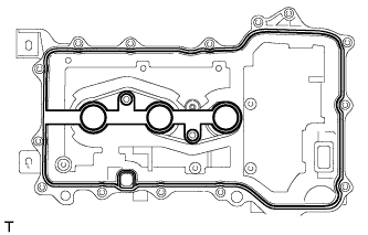
Remove the gasket from the cylinder head cover sub-assembly.
-
-
REMOVE VENTILATION VALVE SUB-ASSEMBLY
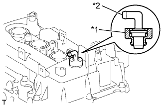
Text in Illustration *1 Grommet *2 Ventilation Valve Sub-Assembly
-
Remove the ventilation valve.
-
Remove the grommet.
-
-
REMOVE OIL PAN DRAIN PLUG
-
Remove the drain plug.
-
Remove the gasket.
-
-
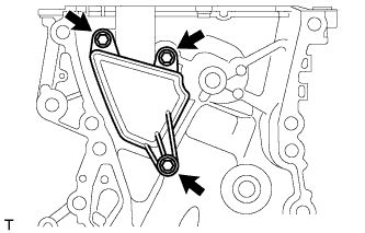
REMOVE OIL FILTER BRACKET STAY
-
Remove the 2 bolts and the oil filter bracket stay.
-
-
REMOVE OIL PAN SUB-ASSEMBLY
-
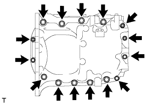
Remove the 12 bolts and 3 nuts.
-
Text in Illustration *1 Oil Pan Seal Cutter Using an oil pan seal cutter, remove the oil pan.
Note
Be careful not to damage the contact surfaces of the oil pan.
-
-
REMOVE OIL STRAINER SUB-ASSEMBLY
-
Remove the 2 bolts and the oil strainer.
-
Remove the gasket.
-
-
REMOVE WATER VALVE
-
Remove the 2 bolts and the water valve.
-
Remove the gasket.
-
-
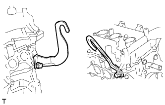
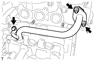
REMOVE NO. 1 WATER BY-PASS PIPE
-
Remove the bolt, the 2 nuts, and the No. 1 water by-pass pipe from the cylinder head and cylinder block.
-
Remove the gasket from the cylinder head.
-
Remove the gasket from the No. 1 water by-pass pipe.
-
-
REMOVE WATER INLET
-
Remove the 2 nuts and the water inlet.
-
-
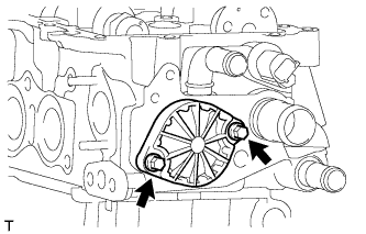
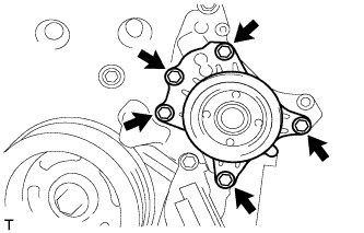
REMOVE WATER PUMP ASSEMBLY
-
Remove the 5 bolts and the water pump assembly.
-
Remove the gasket.
-
-
REMOVE OIL FILTER SUB-ASSEMBLY
-
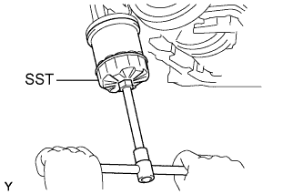
Using SST, remove the oil filter.
- SST
- 09228-06501
-
-
REMOVE OIL FILTER BRACKET
-
Remove the 2 bolts and the oil filter bracket.
-
Remove the gasket.
-
-
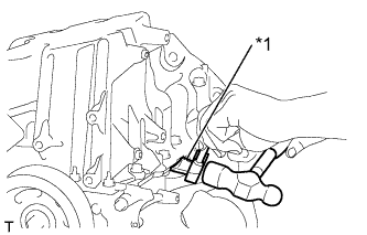
REMOVE TIMING GEAR COVER TIGHT PLUG
Text in Illustration *1 8 mm Socket Hexagon Wrench
-
Using an 8 mm socket hexagon wrench, remove the timing gear cover tight plug.
-
-
SET NO. 1 CYLINDER TO TDC/COMPRESSION
-
Turn the crankshaft pulley clockwise to align the timing mark on the pulley with the timing pointer of the timing chain cover.
Text in Illustration *1 Timing Mark *2 Timing Pointer -
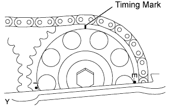
Make sure that the timing mark of the camshaft sprocket is at the top.
-
-
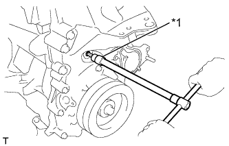
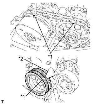
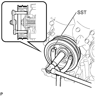
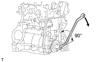
REMOVE CRANKSHAFT PULLEY
-
Using SST, hold the pulley in place and loosen the pulley bolt.
- SST
- 09960-10010 ( 09962-01000, 09963-01000 )
-
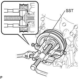
Using SST, remove the crankshaft pulley and pulley bolt.
- SST
- 09950-40011 ( 09951-04010, 09953-04030, 09958-04011, 09955-04011, 09954-04010, 09952-04010 )
-
-
REMOVE TIMING CHAIN OR BELT COVER SUB-ASSEMBLY
-
Remove the 12 bolts.
-
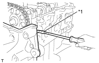
Text in Illustration *1 Protective Tape Using a screwdriver with its tip wrapped in protective tape, remove the timing chain cover by prying between the timing cover and cylinder head or cylinder block.
Note
Do not damage the contact surfaces of the cylinder head, cylinder block and timing chain cover.
-
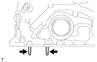
Remove the 2 stud bolts.
-
-
REMOVE TIMING CHAIN OR BELT COVER OIL SEAL
Text in Illustration *1 Protective Tape
-
Using a screwdriver with its tip wrapped in protective tape, pry out the oil seal.
-
-
REMOVE VENTILATION CASE SUB-ASSEMBLY
-
Remove the 3 bolts and the ventilation case sub-assembly.
-
-
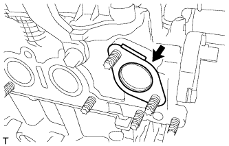
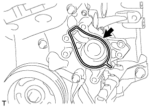
REMOVE OIL PUMP GASKET
-
Remove the oil pump gasket.
-
-
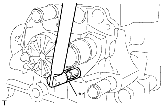
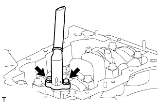
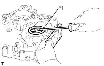
REMOVE NO. 1 CHAIN TENSIONER ASSEMBLY
-
Turn the stopper plate of the chain tensioner clockwise and push in the plunger with the lock released.
Text in Illustration *1 Stopper Plate -
Text in Illustration *1 Hexagon Wrench *2 Stopper Plate Insert a hexagon wrench into the hole in the stopper plate to lock with the plunger pushed in.
-
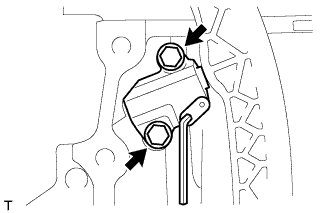
Remove the 2 bolts and the timing chain tensioner.
-
-
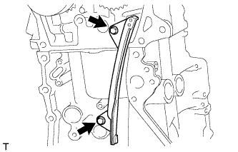
REMOVE TIMING CHAIN TENSION ARM

-
Remove the bolt and the chain tensioner arm.
-
-
REMOVE CHAIN SUB-ASSEMBLY
-
REMOVE TIMING CHAIN GUIDE
-
Remove the 2 bolts and the timing chain guide.
-
-
REMOVE CRANKSHAFT TIMING GEAR OR SPROCKET
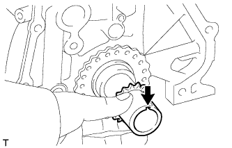
-
Remove the crankshaft timing chain gear or sprocket from the crankshaft.
-
-
REMOVE CRANKSHAFT STRAIGHT PIN
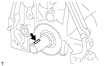
-
Remove the crankshaft straight pin from the crankshaft.
-
-
REMOVE CAMSHAFT TIMING SPROCKET ASSEMBLY
-
Slightly turn the crankshaft clockwise.
Note
Do not allow the lifted valve and piston to come into the contact with each other when removing the camshaft.
-
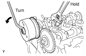
Remove the bolt from the sprocket while holding the hexagonal portion of the camshaft.
-
Remove the camshaft timing sprocket from the camshaft.
-
-
REMOVE CAMSHAFT TIMING GEAR OR SPROCKET
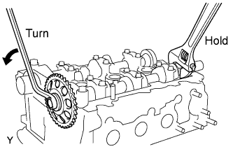
-
Remove the bolt from the gear while holding the hexagonal portion of the No. 2 camshaft.
-
Remove the camshaft timing gear from No. 2 camshaft.
-
-
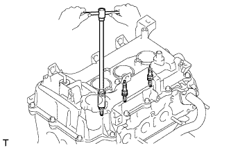
REMOVE CAMSHAFTS
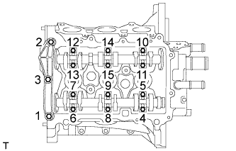
-
Remove the 15 bolts in the order shown in the illustration.
-
Remove the No. 1 camshaft bearing cap and No. 2 camshaft bearing caps.
-
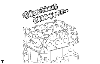
Remove the 2 camshafts.
-
-
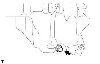
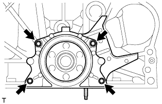
REMOVE ENGINE REAR OIL SEAL RETAINER
-
Remove the 4 bolts, and remove the oil seal retainer.
-
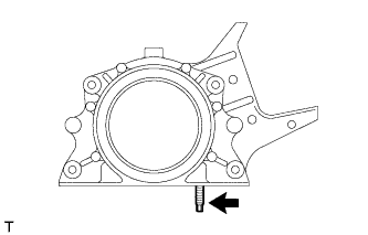
Remove the stud bolt.
-
-
REMOVE ENGINE REAR OIL SEAL
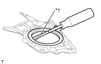
Text in Illustration *1 Protective Tape
-
Using a screwdriver with its tip wrapped in protective tape, pry out the oil seal.
-
-
REMOVE VALVE LIFTER
-
Remove the 12 valve lifters.
Note
-
Record the inscribed mark on the valve lifters for each valve after removing them.
-
Arrange the valve lifters for each cylinder in order.
-
-
-
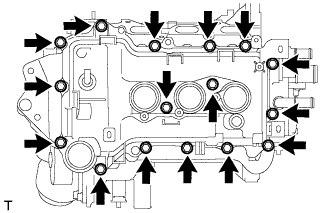
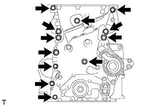
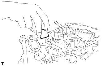
REMOVE CYLINDER HEAD SUB-ASSEMBLY
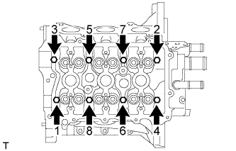
-
Using several steps, uniformly loosen and remove the 8 cylinder head bolts and 8 plate washers with an 8 mm bi-hexagon wrench in the sequence shown in the illustration.
Note
-
Head warpage or cracking could result from removing the bolts in the wrong order.
-
Do not drop the washers into the cylinder head.
-
-
Remove the cylinder head from the cylinder block.
-
-
REMOVE CYLINDER HEAD GASKET
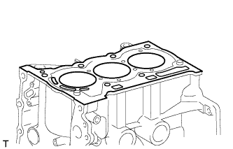
-
Remove the cylinder head gasket.
-