ДВИГАТЕЛЬ В СБОРЕ УСТАНОВКА

Note
-
When the transaxle is removed, be sure to use a new clutch release with bearing cylinder and new installation bolts. Removal of the transaxle allows the compressed clutch release with bearing cylinder to return to its original position, and dust from the moving section could damage the seal of the clutch release with bearing cylinder, possibly causing clutch fluid leaks.
-
After replacing the engine assembly, perform the both "injector Compensation" and "Pilot Quantity Learning Values Reset" functions using the intelligent tester.
-
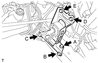
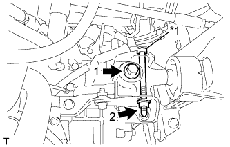
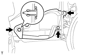
INSTALL TRANSVERSE ENGINE ENGINE MOUNTING INSULATOR
-
Temporarily tighten the bolt A.
-
Temporarily tighten the bolt E.
-
Tighten the bolt B and bolt C.
- Torque:
- 52 N*m { 530 kgf*cm, 38 ft.*lbf }
-
Tighten the bolt A.
- Torque:
- 52 N*m { 530 kgf*cm, 38 ft.*lbf }
-
Tighten the bolt D and bolt E and install the transverse engine engine mounting insulator.
- Torque:
- 52 N*m { 530 kgf*cm, 38 ft.*lbf }
-
-
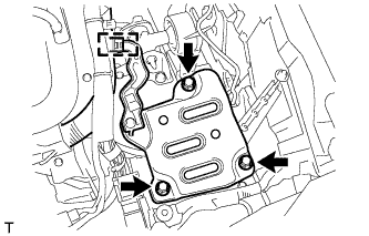
INSTALL REAR BATTERY BRACKET REINFORCEMENT
-
Install the rear battery bracket reinforcement with the 2 bolts.
- Torque:
- 17 N*m { 175 kgf*cm, 13 ft.*lbf }
-
-
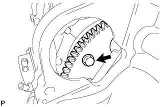
INSTALL DRIVE PLATE AND RING GEAR SUB-ASSEMBLY (for CVT)
-
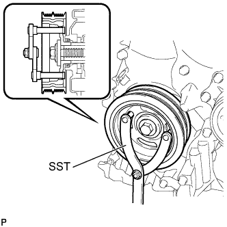
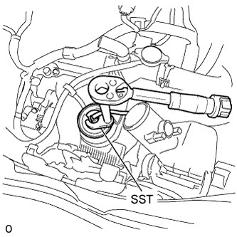
Using SST, hold the crankshaft.
- SST
- 09960-10010 ( 09962-01000, 09963-01000 )
-
Clean the 6 bolts and the 6 bolt holes.
-
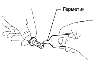
Apply adhesive to 2 or 3 threads of the bolt end.
Adhesive Toyota Genuine Adhesive 1324, Three Bond 1324 or equivalent. -
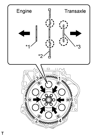
Text in Illustration *1 Front Drive Spacer *2 Drive Plate *3 Rear Drive Plate Spacer Install the front drive plate spacer.
Tech Tips
The front spacer is reversible.
-
Install the drive plate and rear drive plate spacer onto the crankshaft.
-
In several steps, uniformly install and tighten the 6 bolts in the sequence shown in the illustration.
- Torque:
- 78 N*m { 800 kgf*cm, 58 ft.*lbf }
-
-
INSTALL CONTINUOUSLY VARIABLE TRANSAXLE ASSEMBLY (for CVT)
-
Text in Illustration *1 Knock Pin Confirm that 2 knock pins are on the transaxle contact surface of the engine cylinder block before transaxle installation.
-
Apply clutch spline grease to the round of the crankshaft contact surface (*3) with the torque converter centerpiece.
Text in Illustration *2 Crankshaft Clutch spline grease Toyota Genuine Clutch Spline Grease or equivalent Maximum spread Approximately 1 g (0.353 oz) -
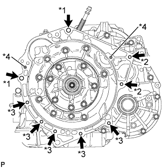
- Torque:
- *1
- 64 N*m { 653 kgf*cm, 47 ft.*lbf }
- *2
- 37 N*m { 377 kgf*cm, 27 ft.*lbf }
- *3
- 39 N*m { 398 kgf*cm, 29 ft.*lbf }
Maintain the engine and CVT in a horizontal position, align the knock pins and holes*4, and tighten the 9 bolts shown the illustration.
- Torque:
- *1
- 64 N*m { 653 kgf*cm, 47 ft.*lbf }
- *2
- 37 N*m { 377 kgf*cm, 27 ft.*lbf }
- *3
- 39 N*m { 398 kgf*cm, 29 ft.*lbf }
Note
-
Confirm that there are 2 knock pins on the fitting surface of the engine block before installing the CVT.
-
Do not twist or apply excessive force to the CVT.
-
Check that the torque converter rotates smoothly after installation of the CVT.
Tech Tips
-
*1: 45 mm (1.77 in.)
-
*2: 45 mm (1.77 in.)
-
*3: 35 mm (1.38 in.)
Bolt length
-
-
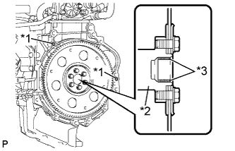
INSTALL DRIVE PLATE AND TORQUE CONVERTER CLUTCH SETTING BOLT (for CVT)
-
Clean and degrease the 6 drive plate and torque converter setting bolts.
-
Apply adhesive to 2 or 3 threads on the ends of the 6 torque converter set bolts.
Text in Illustration *1 Adhesive Adhesive Toyota Genuine Adhesive 1324, Three Bond 1324 or equivalent -
Use SST to hold the crankshaft pulley in place.
- SST
- 09960-10010 ( 09962-01000, 09963-01000 )
-
Install the 6 torque converter set bolts.
- Torque:
- 28 N*m { 286 kgf*cm, 21 ft.*lbf }
Tech Tips
Tighten the black-colored bolt first, and then tighten the 5 silver-colored bolts.
-
-
INSTALL STARTER ASSEMBLY
-
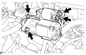
Install the starter assembly with the 2 bolts.
- Torque:
- 37 N*m { 377 kgf*cm, 27 ft.*lbf }
-
Connect the connector.
-
Connect the cable to terminal 30 with the nut.
- Torque:
- 9.8 N*m { 100 kgf*cm, 87 in.*lbf }
-
Close the terminal cap.
-
-
INSTALL FLYWHEEL SUB-ASSEMBLY (for Manual Transaxle)
-
Using SST, hold the crankshaft.
- SST
- 09960-10010 ( 09962-01000, 09963-01000 )
-
Clean the 6 bolts and the 6 bolt holes.
-
Apply adhesive to 2 or 3 threads of the bolt end.
Adhesive Toyota Genuine Adhesive 1324, Three Bond 1324 or equivalent. -
Install the flywheel sub-assembly with the 6 bolts in the order shown in the illustration.
- Torque:
- 78 N*m { 800 kgf*cm, 58 ft.*lbf }
-
-
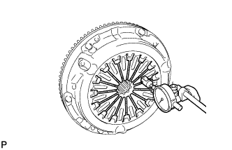
INSTALL CLUTCH DISC ASSEMBLY (for Manual Transaxle)
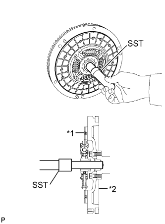
Text in Illustration *1 Clutch disc *2 Flywheel
-
Insert SST into the clutch disc assembly, and then insert them both into the flywheel sub-assembly.
- SST
- 09301-00210
Note
Insert the clutch disc assembly in the correct direction.
-
-
INSTALL CLUTCH COVER ASSEMBLY (for Manual Transaxle)
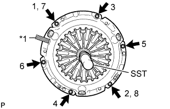
Text in Illustration *1 Matchmark
-
Align the matchmark on the clutch cover assembly with that on the flywheel sub-assembly.
-
Following the procedures shown in the illustration, tighten the 6 bolts in order, starting with the bolt located near the knock pin at the top.
- SST
- 09301-00210
- Torque:
- 19 N*m { 195 kgf*cm, 14 ft.*lbf }
Tech Tips
-
Following the order in the illustration, tighten the bolts evenly one at a time.
-
Move SST up and down, right and left lightly after checking that the disc is in the center, and tighten the bolts.
-
-
INSPECT AND ADJUST CLUTCH COVER ASSEMBLY (for Manual Transaxle)
-
Using a dial indicator with a roller instrument, check the diaphragm spring tip alignment.
Maximum non-alignment 0.5 mm (0.020 in.) -
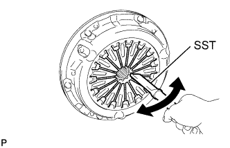
If the alignment is not as specified, using SST, adjust the diaphragm spring tip alignment.
- SST
- 09333-00013
-
-
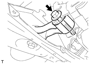
INSTALL CLUTCH RELEASE WITH BEARING CYLINDER ASSEMBLY (for Manual Transaxle)
-
Clean and degrease all installation surfaces for the clutch release with bearing cylinder assembly.
-
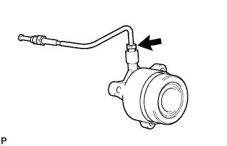
Temporarily tighten the bleeder clutch release tube onto the clutch release with bearing cylinder assembly.
-
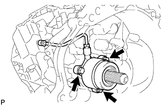
Install the new clutch release with the bearing cylinder with the 3 new bolts.
Note
-
The clutch release with bearing cylinder assembly and installation bolts cannot be reused and must be replaced with new ones.
-
Clean and degrease all installation surfaces and make sure the clutch release with bearing cylinder assembly fits securely with the transaxle during installation. The first bolt should be tightened by hand the clutch release with bearing cylinder assembly.
-
Ensure that none of the clutch disc spline grease adheres to the clutch release with bearing cylinder assembly.
-
The clutch release with bearing cylinder assembly cannot be disassembled.
- Torque:
- 23 N*m { 229 kgf*cm, 17 ft.*lbf }
-
-
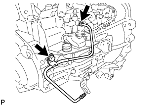
Install the clutch tube boot onto the transaxle.
-
Install the release cylinder bleeder plug onto the clutch release bleeder.
- Torque:
- 8.4 N*m { 86 kgf*cm, 74 in.*lbf }
-
Install the release cylinder bleeder plug cap.
-
Text in Illustration *1 Bleeder clutch release tube *2 Clutch release bleeder Temporarily tighten the bleeder clutch release tube onto the clutch release bleeder.
-
Temporarily tighten the 2 bolts and install the clutch release bleeder.
-
Using a union nut wrench 10 mm, install the bleeder clutch release tube.
- Torque:
- 15 N*m { 155 kgf*cm, 11 ft.*lbf }
Note
Use the formula to calculate special torque values for situations when union nut wrench is combined with a torque wrench Click here.
-
-
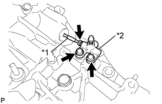
INSTALL CLUTCH RELEASE BLEEDER SUB-ASSEMBLY (for Manual Transaxle)
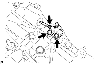
-
Separate the bleeder clutch release tube from the clutch release bleeder.
-
Remove the 2 bolts and the clutch release bleeder.
-
-
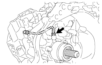
INSPECT CLUTCH PIPE LINE (for Manual Transaxle)
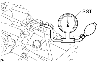
-
Using SST, apply pressure of 0.1 MPa to the clutch pipe location shown in the illustration and confirm that pressure is maintained for 15 seconds or more.
- SST
- 09992-00242
If the pressure drops, replace the bleeder clutch release tube.
-
-
INSTALL CLUTCH RELEASE BLEEDER SUB-ASSEMBLY (for Manual Transaxle)
-
Text in Illustration *1 Bleeder clutch release tube *2 Clutch release bleeder Temporarily tighten the bleeder clutch release tube onto the clutch release bleeder.
-
Install the 2 bolts and clutch release bleeder.
- Torque:
- 17 N*m { 170 kgf*cm, 12 ft.*lbf }
-
Using a union nut wrench 10 mm, install the bleeder clutch release tube.
- Torque:
- 15 N*m { 155 kgf*cm, 11 ft.*lbf }
Note
Use the formula to calculate special torque values for situations when union nut wrench is combined with a torque wrench Click here.
-
-
INSTALL BLEEDER TO ACCUMULATOR TUBE (for Manual Transaxle)
-
Install the bleeder clutch release tube with the bolt.
- Torque:
- 12 N*m { 122 kgf*cm, 9 ft.*lbf }
-
Using a union nut wrench 10 mm, install the bleeder clutch release tube.
- Torque:
- 15 N*m { 155 kgf*cm, 11 ft.*lbf }
Note
Use the formula to calculate special torque values for situations when union nut wrench is combined with a torque wrench Click here.
-
-
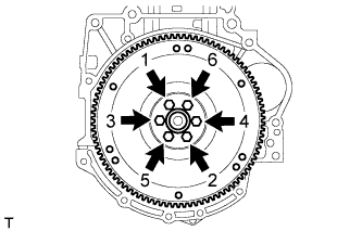
INSTALL MANUAL TRANSAXLE ASSEMBLY (for Manual Transaxle)
-
Make sure that the knock pins are not loose, bent, damaged or scratched and then install the transaxle onto the engine with the contact surfaces of the engine and transaxle flat against each other.
-
Align the input shaft with the clutch disc and install the manual transaxle onto the engine.
-
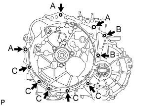
Install the 10 bolts.
- Torque:
- Bolt A
- 64 N*m { 653 kgf*cm, 47 ft.*lbf }
- Bolt B
- 37 N*m { 377 kgf*cm, 27 ft.*lbf, (for Flange Bolt) }
- 33 N*m { 337 kgf*cm, 24 ft.*lbf, (for Bolt with Washer) }
- Bolt C
- 39 N*m { 398 kgf*cm, 29 ft.*lbf }
Note
Insert knock pins into the knock pin holes securely so that the end face of the transaxle assembly fits close against the engine assembly before tightening the bolts.
-
-
INSTALL EXHAUST MANIFOLD
-
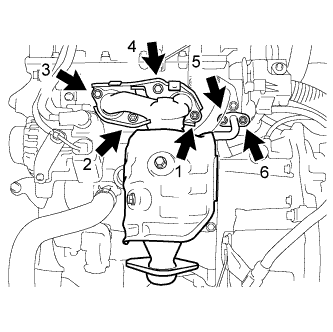
Place the 2 new gaskets and install the exhaust manifold, tightening the nuts and bolts in the sequence shown in the illustration.
- Torque:
- 28 N*m { 286 kgf*cm, 21 ft.*lbf }
-
-
INSTALL NO. 1 EXHAUST MANIFOLD HEAT INSULATOR
-
Install the No. 1 exhaust manifold heat insulator, tightening the nuts and bolts in the sequence shown in the illustration.
- Torque:
- 8.5 N*m { 87 kgf*cm, 75 in.*lbf }
-
-
INSTALL AIR FUEL RATIO SENSOR
-
Using SST, install the air fuel ratio sensor to the exhaust manifold.
- SST
- 09224-00010
- Torque:
- without SST
- 44 N*m { 449 kgf*cm, 32 ft.*lbf }
- with SST
- 40 N*m { 408 kgf*cm, 30 ft.*lbf }
Note
-
The "with SST" torque value is effective when using SST with a fulcrum length of 30 mm (1.18 in.).
-
The "with SST" torque value is effective when using a torque wrench with a fulcrum length of 300 mm (11.81 in.) Click here.
-
This torque value is effective when SST is parallel to the torque wrench.
-
Install the wire harness clamp and connect the air fuel ratio sensor connector.
-
-
INSTALL MANIFOLD STAY
-
After temporarily tightening the manifold stay until the nut is firm against the exhaust manifold, fully tighten the manifold stay to the block with the 2 bolts and then fully tighten the nut on the exhaust manifold side.
- Torque:
- 24 N*m { 245 kgf*cm, 18 ft.*lbf }
-
-
INSTALL ENGINE ASSEMBLY WITH TRANSAXLE
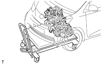
-
Set the engine assembly with transaxle on the engine lifter.
-
Operate the engine lifter and lift the engine assembly with transaxle to the position where the engine mounting insulator RH and transverse engine engine mounting insulator can be installed.
CAUTION:
Do not raise the engine more than necessary. If the engine is raised excessively, the vehicle may also be lifted up.
Note
-
Make sure that the engine is clear of all wiring and hoses.
-
While raising the engine into the vehicle, do not allow it to contact the vehicle.
-
-
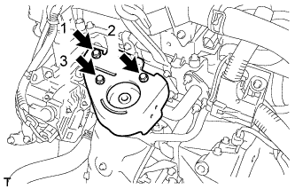
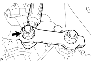
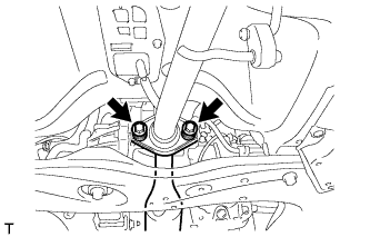
Text in Illustration *1 Through Bolt Temporarily install the transverse engine engine mounting insulator with the through bolt.
-
Tighten the through bolt and bolt in the order shown in the illustration.
- Torque:
- Through bolt
- 52 N*m { 530 kgf*cm, 38 ft.*lbf }
- Torque:
- Bolt
- 64 N*m { 653 kgf*cm, 47 ft.*lbf }
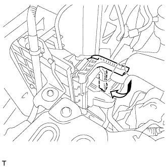
-
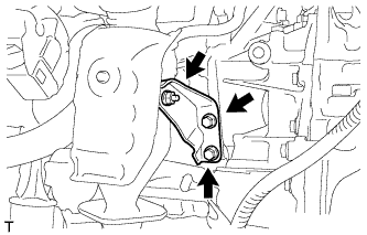
Temporarily tighten the bolt A.
-
Tighten the 2 bolts on the vehicle side in the sequence shown in the illustration.
- Torque:
- 52 N*m { 530 kgf*cm, 38 ft.*lbf }
-
Fully tighten the bolt A.
- Torque:
- 52 N*m { 530 kgf*cm, 38 ft.*lbf }
-
Tighten the bolt and the 2 nuts on the engine side and install the engine mounting insulator RH.
- Torque:
- 52 N*m { 530 kgf*cm, 38 ft.*lbf }
-
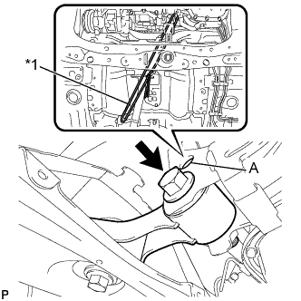
Text in Illustration *1 Rope Secure the hole (A) shown in the illustration and the body with a piece of rope.
Note
When installing the engine assembly with the transaxle, make sure that the engine assembly does not move to the vehicle front, to prevent it from contacting other parts.
-
Connect the vacuum hose to the vacuum switching valve.
-
Remove the 2 bolts and the 2 engine hangers.
-
-
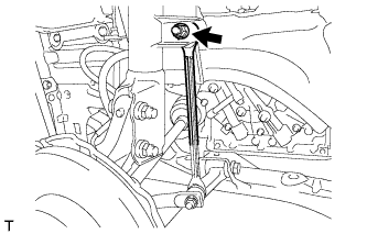
INSTALL ENGINE MOVING CONTROL ROD
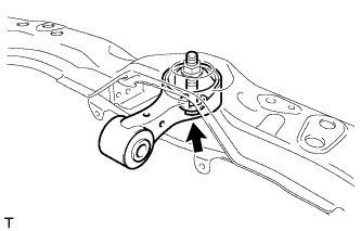
-
Установите тягу управления перемещением двигателя и закрепите ее болтом.
- Torque:
- 100 Н*м { 1020 кгс*см, 74 фунт-сила-дюйма }
-
-
INSTALL ENGINE MOVING CONTROL ROD COVER (for Cold Area)
-
Закрепите крышку тяги управления перемещением двигателя с помощью 2 фиксаторов.
-
-
INSTALL COOLER COMPRESSOR ASSEMBLY
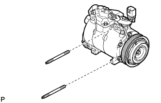
-
Установите компрессор и закрепите его 2 шпильками с помощью торцевого ключа "TORX" (Е8).
- Torque:
- 15 Н*м { 153 кгс*см, 11 фунт-сила-дюймов }
-
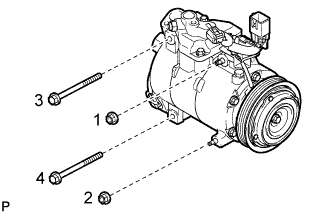
Закрепите компрессор 2 болтами и 2 гайками.
- Torque:
- 25 Н*м { 250 кгс*см, 18 фунт-сила-дюймов }
Tech Tips
Затягивайте болты и гайки в порядке, показанном на рисунке.
-
Подсоедините разъем.
-
-
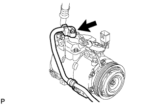
INSTALL DISCHARGE HOSE SUB-ASSEMBLY
-
Снимите виниловую ленту с трубопровода высокого давления.
-
Нанесите необходимое количество компрессорного масла на новое кольцевое уплотнение и пригоночную поверхность компрессора системы кондиционирования.
Компрессорное масло ND-OIL 8 или аналогичное -
Установите кольцевое уплотнение на трубопровод высокого давления.
-
Подсоедините трубопровод высокого давления к компрессору системы кондиционирования и закрепите его болтом.
- Torque:
- 9,8 Н*м { 100 кгс*см, 87 фунт-сила-дюймов }
-
Установите кронштейн трубопровода высокого давления и закрепите его болтом.
- Torque:
- 9,8 Н*м { 100 кгс*см, 87 фунт-сила-дюймов }
-
-
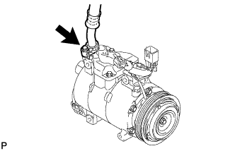
INSTALL SUCTION HOSE SUB-ASSEMBLY
-
Снимите виниловую ленту с трубопровода низкого давления.
-
Нанесите необходимое количество компрессорного масла на новое кольцевое уплотнение и пригоночную поверхность компрессора системы кондиционирования.
Компрессорное масло ND-OIL 8 или аналогичное -
Установите кольцевое уплотнение на трубопровод низкого давления.
-
Подсоедините трубопровод низкого давления к компрессору системы кондиционирования и закрепите болтом.
- Torque:
- 9,8 Н*м { 100 кгс*см, 87 фунт-сила-дюймов }
-
-
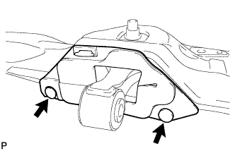
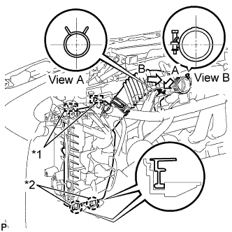
INSTALL FRONT FRAME ASSEMBLY
-
Поддомкратьте переднюю раму в сборе с помощью домкрата и 4 деревянных брусков.
-
Предварительно закрепите переднюю раму в сборе на кузове 6 болтами.
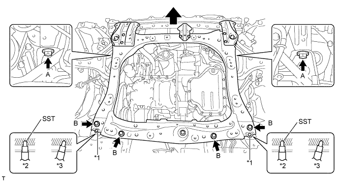
Обозначения на рисунке *1 Базовые отверстия *2 OK *3 NG Болт Длина подголовка (мм) А 38 B 69 -
По очереди вставляя SST в базовые отверстия правой и левой передних рам в сборе, в несколько этапов затяните болты A и B с обеих сторон с номинальным моментом затяжки.
- SST
- 09670-00011
- Torque:
- 108 Н*м { 1101 кгс*см, 80 фунт-сила-дюймов, Для болта A }
- 120 Н*м { 1224 кгс*см, 89 фунт-сила-дюймов, для болта B }
Note
-
Вставляйте SST в базовые отверстия, держа его вертикально.
-
Если не удается вставить SST в базовые отверстия вертикально, ослабьте все болты и снова вставьте SST.
-
Установите тягу управления перемещением двигателя на регулирующий кронштейн опоры двигателя и закрепите ее болтом.
- Torque:
- 120 Н*м { 1224 кгс*см, 89 фунт-сила-дюймов }
-
Снимите жесткий трос с регулирующего кронштейна опоры двигателя и кузова.
-
-
INSTALL FRONT DRIVE SHAFT ASSEMBLY LH
-
Смажьте шлицевую часть внутреннего шарнира трансмиссионным маслом.
-
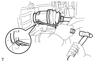
Выровняйте шлицы внутреннего шарнира и с помощью отвертки и молотка установите приводной вал.
Note
-
Поверните стопорное кольцо отверстия внутреннего шарнира переднего приводного вала вырезом вниз.
-
Будьте осторожны, чтобы не повредить сальник.
-
Действуйте осторожно, чтобы не повредить чехол внутреннего шарнира.
Tech Tips
Проверьте надежность посадки приводного вала по силе противодействия и звуку.
-
-
-
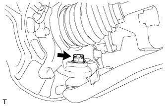
INSTALL FRONT DRIVE SHAFT ASSEMBLY RH
-
Смажьте шлицевую часть вала внутреннего шарнира трансмиссионным маслом.
-
Установите приводной вал в сборе.
-
С помощью плоскогубцев для насоса системы охлаждения установите новое пружинное стопорное кольцо отверстия кронштейна подшипника.
Note
Будьте осторожны, чтобы не повредить чехол и сальник.
-
Вверните новый болт.
- Torque:
- 32 Н*м { 330 кгс*см, 24 фунт-сила-дюйма }
Note
Прежде чем вворачивать новый болт, убедитесь, что на конце болта имеется резина. Если на болте нет резины, используйте другой новый болт.
-
-
INSTALL FRONT AXLE ASSEMBLY LH
-
Сдвиньте переднюю полуось наружу автомобиля, чтобы совместить с ней шлицевую часть приводного вала, и вставьте переднюю полуось.
Note
-
Не выдвигайте ступицу переднего колеса к наружной части автомобиля дальше, чем это необходимо.
-
Действуйте осторожно, чтобы не повредить чехол наружного шарнира.
-
Убедитесь, что на роторе датчика частоты вращения и поверхности установки нет посторонних веществ.
-
Соблюдайте осторожность, чтобы не повредить ротор датчика частоты вращения.
-
-
-
INSTALL FRONT AXLE ASSEMBLY RH
Tech Tips
The installation procedure for the RH side is the same as that for the LH side.
-
INSTALL FRONT NO. 1 SUSPENSION ARM SUB-ASSEMBLY LOWER LH
-
Установите нижний рычаг на поворотный кулак и закрепите его новой корончатой гайкой.
- Torque:
- 98 Н*м { 999 кгс*см, 72 фунт-сила-дюйма }
Note
Если отверстия фиксатора не совпадают, доверните гайку еще на 60°.
-
Установите новый фиксатор.
-
-
INSTALL FRONT NO. 1 SUSPENSION ARM SUB-ASSEMBLY LOWER RH
Tech Tips
The installation procedure for the RH side is the same as that for the LH side.
-
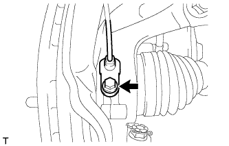
INSTALL FRONT STABILIZER LINK ASSEMBLY LH
-
Установите стойку стабилизатора и закрепите ее гайкой.
- Torque:
- 74 Н*м { 755 кгс*см, 55 фунт-сила-дюймов }
Tech Tips
Если шаровой шарнир поворачивается вместе с гайкой, удерживайте палец шарового шарнира с помощью торцевого шестигранного ключа на 6 мм.
-
-
INSTALL FRONT STABILIZER LINK ASSEMBLY RH
Tech Tips
The installation procedure for the RH side is the same as that for the LH side.
-
INSTALL FRONT SPEED SENSOR LH
-
Установите датчик частоты вращения на поворотный кулак и закрепите его болтом.
- Torque:
- 8,5 Н*м { 87 кгс*см, 75 фунт-сила-дюймов }
Note
-
Убедитесь, что на конце датчика частоты вращения и поверхности установки нет посторонних веществ.
-
Устанавливая датчик скорости, не поворачивайте его относительно исходного угла установки.
-
Установите гибкий шланг и датчик частоты вращения и закрепите их болтом.
- Torque:
- Болт A
- 29 Н*м { 296 кгс*см, 21 фунт-сила-дюйм }
- Болт B
- 29 Н*м { 300 кгс*см, 22 фунт-сила-дюйма }
Note
Установите гибкий шланг и датчик частоты вращения, не перекручивая их.
-
-
INSTALL FRONT SPEED SENSOR RH
Tech Tips
The installation procedure for the RH side is the same as that for the LH side.
-
INSTALL FRONT AXLE SHAFT LH NUT
-
Очистите резьбовые части приводного вала и гайки ступицы колеса растворителем, не оставляющим осадка.
Note
-
Обязательно выполните эту операцию для нового приводного вала.
-
Не допускайте попадания масла и посторонних веществ на резьбовую часть.
-
-
С помощью удлиненной торцевой головки на 30 мм установите новую гайку ступицы колеса.
- Torque:
- 216 Н*м { 2203 кгс*см, 159 фунт-сила-дюймов }
-
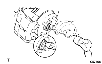
С помощью молотка и зубила накерните гайку ступицы колеса.
-
-
INSTALL FRONT AXLE SHAFT RH NUT
Tech Tips
The installation procedure for the RH side is the same as that for the LH side.
-
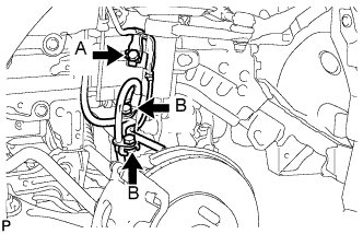
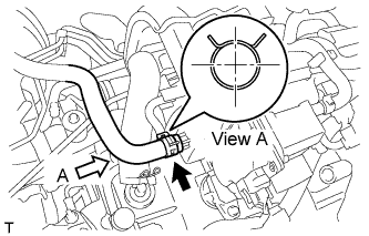
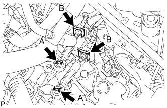
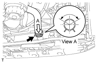
INSTALL UNION TO CHECK VALVE HOSE
-
Install the union to check valve hose with the clip.
Tech Tips
Install the clip as shown in the illustration.
-
-
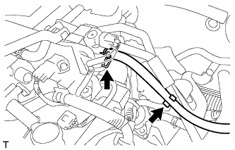
INSTALL NO. 1 FUEL VAPOR FEED HOSE
-
Install the No. 1 fuel vapor feed hose with the clip.
-
Install the No. 1 fuel vapor feed hose to the hose clamp.
-
-
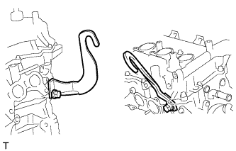
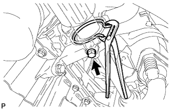
INSTALL NO. 1 CLUTCH HOSE (for Manual Transaxle)
-
Install the a new clip.
-
Using a union nut wrench 10 mm, connect the No. 1 clutch hose to the clutch release cylinder to flexible hose tube.
- Torque:
- 15 N*m { 155 kgf*cm, 11 ft.*lbf }
Note
Use the formula to calculate special torque values for situations where union nut wrench is combined with a torque wrench Click here.
-
-
INSTALL TRANSMISSION CONTROL CABLE ASSEMBLY (for CVT)
-
Install the transmission control cable to the No. 1 transmission control cable bracket, using a new clip.
-
Using the nut, connect the transmission control cable to the transmission control shaft lever.
- Torque:
- 12 N*m { 122 kgf*cm, 9 ft.*lbf }
-
-
INSTALL TRANSMISSION CONTROL CABLE ASSEMBLY (for Manual Transaxle)
-
Install the 2 new clips <B> onto the transmission control cable.
-
Connect the transmission control cable with the 2 clips <A> onto the transaxle.
-
-
INSTALL HEATER WATER HOSE OUTLET
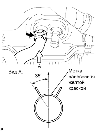
-
Установите выходной патрубок отопителя на блок отопителя.
Tech Tips
При установке расположите хомут шланга и метку под правильным углом.
-
-
INSTALL HEATER WATER HOSE INLET
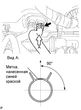
-
Установите входной патрубок отопителя на блок отопителя.
Tech Tips
При установке расположите хомут шланга и метку под правильным углом.
-
-
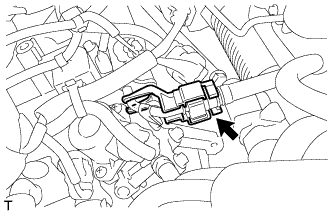
INSTALL FUEL TUBE SUB-ASSEMBLY
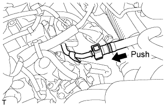
-
Push the tube connector into the pipe until the tube connector makes a "click" sound.
Note
-
Check whether there is any damage or foreign matter on the connected part of the fuel pipe.
-
Check that the fuel tube connector and the pipe are securely connected by pulling on them after connecting.
-
-
-
INSTALL EFI FUEL PIPE CLAMP
-
Install the No. 1 fuel pipe clamp.
-
-
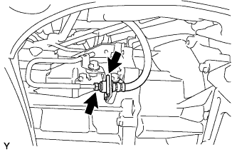
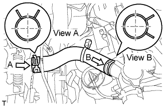
CONNECT NO. 2 RADIATOR HOSE
-
Connect the No. 2 radiator hose with the clip.
Tech Tips
Install the clip as shown in the illustration.
-
-
INSTALL NO. 3 RADIATOR HOSE
-
Install the No. 3 radiator hose with the 2 clips.
Tech Tips
Install the clip as shown in the illustration.
-
-
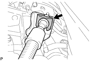
CONNECT RADIATOR RESERVOIR TANK HOSE
-
Connect the radiator reservoir tank hose with the clip.
Tech Tips
Install the clip as shown in the illustration.
-
-
INSTALL FRONT BUMPER COVER
-
Установите облицовку переднего бампера и введите в зацепление 6 захватов.
-
Затяните 4 винта.
-
Установите 5 фиксаторов.
-
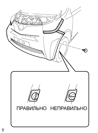
Установите фиксатор штифта.
Note
Вставьте фиксатор штифта так, чтобы его прорезь располагалась вертикально. Не поворачивайте фиксатор после установки. После установки убедитесь, что прорезь фиксатора расположена вертикально.
Tech Tips
Порядок выполнения работ для левой и правой стороны одинаков.
-
-
INSTALL ENGINE WIRE
-
Connect the earth wire with the bolt.
- Torque:
- 8.0 N*m { 82 kgf*cm, 71 in.*lbf }
-
Connect the 4 engine wire connectors and 2 clamps to the engine room junction block.
-
Connect the engine wire connector to the ECM.
-
Turn the lever and connect the ECM connector.
-
-
INSTALL AIR CLEANER FILTER ELEMENT SUB-ASSEMBLY
-
INSTALL AIR CLEANER AND HOSE
Text in Illustration *1 Clamp *2 Guide
-
Align the 2 hinges with the case guide, to insert the case into the groove, and engage the 2 clamps to install the air cleaner cap.
-
Connect the air cleaner hose with the hose clamp.
- Torque:
- 3.0 N*m { 31 kgf*cm, 27 in.*lbf }
Tech Tips
Install the clip as shown in the illustration.
-
Connect the ventilation hose with the clip
Tech Tips
Install the clip as shown in the illustration.
-
-
INSTALL NO. 2 BATTERY CARRIER
-
Install the No. 2 battery carrier with the 3 bolts.
- Torque:
- 17 N*m { 75 kgf*cm, 13 ft.*lbf }
-
Install the harness clamp.
-
-
INSTALL BATTERY TRAY
-
Install the battery tray.
-
-
INSTALL BATTERY
-
Install the battery onto the vehicle.
-
Install the battery clamp with the 2 nuts.
- Torque:
- 3.5 N*m { 36 kgf*cm, 35 in.*lbf }
-
Connect the cable to the battery terminal.
- Torque:
- 5.0 N*m { 55 kgf*cm, 43 in.*lbf }
-
-
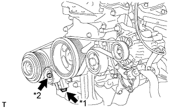
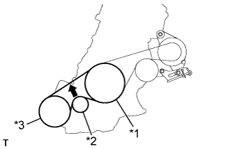
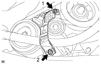
INSTALL FAN AND GENERATOR V BELT
Text in Illustration *1 Crankshaft Pulley *2 Water Pump Assembly *3 Generator Assembly
-
Temporarily install the V-ribbed belt onto each pulley.
Note
-
Before installing the V-ribbed belt, check each pulley for any kind of liquid and chips.
-
Check that the ribs of the V-ribbed belt are correctly fitted into the grooves of the pulleys.
-
-
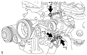
Text in Illustration *1 Bolt B *2 Bolt A *3 Bolt C Turn the bolt B to adjust the tension of the V-ribbed belt.
-
Tighten fixing bolts A and C.
- Torque:
- Bolt A
- 54 N*m { 551 kgf*cm, 40 ft.*lbf }
- Bolt C
- 21 N*m { 214 kgf*cm, 15 ft.*lbf }
-
-
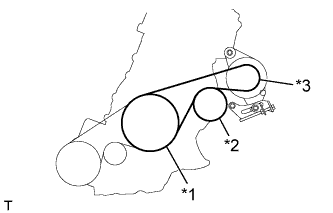
INSTALL NO. 1 V (COOLER COMPRESSOR TO CRANKSHAFT PULLEY) BELT
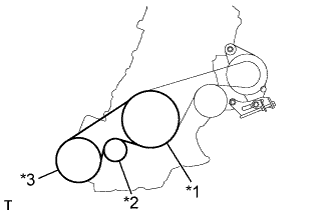
Text in Illustration *1 Crankshaft Pulley *2 Idler Pulley *3 Cooler Compressor Assembly
-
Temporarily install the V-ribbed belt onto each pulley.
Note
-
Before installing the V-ribbed belt, check each pulley for any kind of liquid and chips.
-
Check that the ribs of the V-ribbed belt are correctly fitted into the grooves of the pulleys.
-
-
Text in Illustration *1 Bolt B *2 Bolt A Turn the bolt B to adjust the tension of the V-ribbed belt.
-
Tighten bolt A.
-
-
INSPECT FAN AND GENERATOR V BELT
-
Text in Illustration *1 Crankshaft Pulley *2 Water Pump Pulley *3 Generator Pulley 
Specified Point Check the fan and generator V-ribbed belt deflection (when inspecting a vehicle without the No. 1 engine cover installed).
Deflection Pressing Force
N (kg, Ib)
New Belt
mm (in.)
Used Belt
mm (in.)
10
(10, 22)
8.0 to 10.5
(0.315 to 0.413)
11.0 to 14.0
(0.433 to 0.551)
Note
-
Check the belt deflection between the pulleys at the indicated measurement point (directly between the pulleys).
-
When installing a new belt, set its deflection value as specified.
-
When checking a belt used for over 5 minutes, confirm that the deflection value is within the specified range for a used belt.
-
When reinstalling a belt used for over 5 minutes, check whether its deflection value is within the specified range for a used belt.
-
-
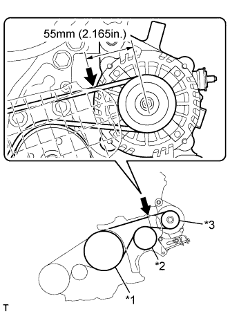
Text in Illustration *1 Crankshaft Pulley *2 Water Pump Pulley *3 Generator Pulley Specified Point Check the fan and generator V-ribbed belt deflection (when inspecting a vehicle while the No. 1 engine cover is installed).
Deflection Pressing Force
N (kg, Ib)
New Belt
mm (in.)
Used Belt
mm (in.)
10
(10, 22)
4.5 to 6.0
(0.177 to 0.236)
6.5 to 7.5
(0.256 to 0.295)
Note
-
Check the belt deflection between the pulleys at the indicated measurement point (on the left side of the generator pulley, 55 mm (2.165 in.) from the center of the pulley).
-
When installing a new belt, set its deflection value as specified.
-
When checking a belt used for over 5 minutes, confirm that the deflection value is within the specified range for a used belt.
-
When reinstalling a belt used for over 5 minutes, check whether its deflection value is within the specified range for a used belt.
-
-
-
INSPECT NO. 1 V (COOLER COMPRESSOR TO CRANKSHAFT PULLEY) BELT
-
Text in Illustration *1 Crankshaft Pulley *2 Idler Pulley *3 Cooler Compressor Assembly Specified Point Check the No. 1 (cooler compressor to crankshaft pulley) belt.
Deflection Pressing Force
N (kg, Ib)
New Belt
mm (in.)
Used Belt
mm (in.)
10
(10, 22)
8.0 to 10.0
(0.315 to 0.394)
11.0 to 14.0
(0.433 to 0.551)
Note
-
Check the No. 1 (cooler compressor to crankshaft pulley) belt deflection at the specified point.
-
When installing a new belt, set its deflection value as specified.
-
When checking a belt used for over 5 minutes, confirm that the deflection value is within the specified range for a used belt.
-
When reinstalling a belt used for over 5 minutes, check whether its deflection value is within the specified range for a used belt.
-
-
-
INSTALL FRONT EXHAUST PIPE ASSEMBLY
-
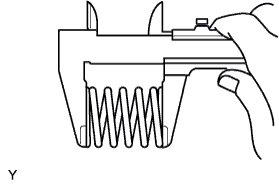
Using a vernier caliper, measure the free length of the compression springs.
Minimum Length Item Length Front 41.5 mm (1.634 in.) Tech Tips
If the length is not as specified, replace the compression spring.
-
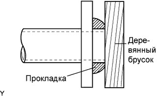
Using a plastic hammer and a wooden block, tap in a new exhaust pipe gasket until its surface is flush with the exhaust manifold.
Note
-
Install the gasket in the correct direction.
-
Do not reuse the gasket.
-
Do not damage the gasket by dropping it, etc.
-
Do not damage the outer surface of the gasket.
-
Do not push in the gasket with the exhaust pipe when connecting it.
-
After the installation, check that the gaps between the flanges of the exhaust manifold and front exhaust pipe assembly are consistent front-to-rear and left-to-right.
-
-
Install the front exhaust pipe assembly to the exhaust manifold with the 2 bolts and the 2 compression springs.
- Torque:
- 43 N*m { 438 kgf*cm, 32 ft.*lbf }
-
Using a vernier caliper, measure the free length of the compression springs.
Minimum Length Item Length Rear 38.5 mm (1.594 in.) Tech Tips
If the length is not as specified, replace the compression spring.
-
Using a plastic hammer and a wooden block, tap in a new exhaust pipe gasket until its surface is flush with the exhaust manifold.
Note
-
Install the gasket in the correct direction.
-
Do not reuse the gasket.
-
Do not damage the gasket by dropping it, etc.
-
Do not damage the outer surface of the gasket.
-
Do not push in the gasket with the exhaust pipe when connecting it.
-
After the installation, check that the gaps between the flanges of the front exhaust pipe assembly and tail exhaust pipe assembly are consistent front-to-rear and left-to-right.
-
-
Install the front exhaust pipe assembly to the tail exhaust pipe assembly with the 2 bolts and the 2 compression springs.
- Torque:
- 43 N*m { 438 kgf*cm, 32 ft.*lbf }
-
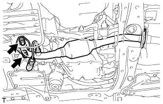
Connect the oxygen sensor connector and engage the clamp.
-
-
INSTALL FRONT WHEELS
-
ADD ENGINE COOLANT
-
Затяните пробку сливного крана радиатора.
-
Снимите крышку водоналивной горловины в сборе.
-
Медленно залейте в радиатор охлаждающую жидкость "TOYOTA Super Long Life Coolant" (SLLC).
Номинальный объем Параметр / Устройство Объем Для моделей с механической трансмиссией 4,3 литра (4,5 кварты США, 3,8 английской кварты) Для моделей с бесступенчатой трансмиссией 4,5 литра (4,8 кварты США, 4,0 английской кварты) Note
Никогда не используйте воду вместо охлаждающей жидкости.
Tech Tips
Автомобили Toyota первоначально заправляются охлаждающей жидкостью TOYOTA SLLC на заводе. Во избежание повреждения системы охлаждения двигателя или других технических проблем разрешается использовать только охлаждающую жидкость "TOYOTA Super Long Life Coolant" или аналогичную высококачественную охлаждающую жидкость на основе этиленгликоля (а не на силикатной, аминовой, нитритной или борнокислой основе), изготовленную по гибридной технологии органических кислот с длительным сроком годности (охлаждающая жидкость, изготовленная по гибридной технологии органических кислот, состоит из низкофосфатных соединений и органических кислот).
-
Несколько раз сожмите рукой входной и выходной патрубки радиатора, а затем проверьте уровень охлаждающей жидкости.
Если уровень охлаждающей жидкости недостаточен, добавьте жидкость.
-
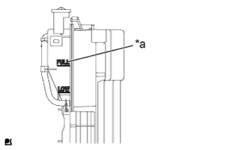
Обозначения на рисунке *a Линия FULL Залейте охлаждающую жидкость в расширительный бачок радиатора до уровня FULL.
-
Установите крышку водоналивной горловины в сборе.
-
Запустите и прогрейте двигатель.
-
Выпустите воздух из системы охлаждения.
Note
-
Перед запуском двигателя установите выключатель системы кондиционирования в положение OFF (ВЫКЛ).
-
Установите температуру кондиционера на уровень MAX (HOT).
-
Установите вентилятор кондиционера в режим LO.
-
Прогревайте двигатель, пока не откроется термостат. Когда термостат откроется, обеспечьте циркуляцию охлаждающей жидкости в течение нескольких минут.
Tech Tips
Момент открывания термостата можно определить, сжав входной патрубок радиатора и отметив вибрации, когда охлаждающая жидкость двигателя начнет поступать в шланг.
CAUTION:
При сжатии патрубка радиатора:
-
Работайте в защитных перчатках.
-
Будьте осторожны: патрубки радиатора горячие.
-
Не прикасайтесь к вентилятору радиатора.
-
-
-
Остановите двигатель и дождитесь, когда охлаждающая жидкость остынет.
-
Снимите крышку водоналивной горловины в сборе и проверьте уровень охлаждающей жидкости.
Если уровень охлаждающей жидкости ниже линии "LOW", повторите вышеперечисленные действия.
-
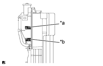
Обозначения на рисунке *a Линия FULL *b Линия LOW После того как уровень охлаждающей жидкости прекратит снижаться, убедитесь, что он находится между линиями FULL и LOW.
Если уровень охлаждающей жидкости недостаточен, долейте ее до отметки "FULL" расширительного бачка.
-
-
ADD ENGINE OIL
-
INSPECT FOR ENGINE COOLANT LEAK
CAUTION:
Для предотвращения ожогов не снимайте крышку водоналивной горловины, пока двигатель и радиатор в сборе не остынут. Тепловое расширение вызывает выброс из радиатора горячей охлаждающей жидкости и пара.
-
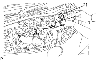
Обозначения на рисунке *1 Приспособление для опрессовки системы охлаждения и проверки пробки радиатора Заполните радиатор охлаждающей жидкостью, а затем подсоедините приспособление для опрессовки системы охлаждения и проверки пробки радиатора.
-
Создайте с помощью приспособления давление 118 кПа (1,2 кгс/см2, 17,1 фунта на кв. дюйм) и убедитесь, что давление не падает.
Если давление снижается, проверьте на наличие утечек шланги, радиатор в сборе и насос системы охлаждения в сборе. Если нет признаков наружной утечки охлаждающей жидкости двигателя, проверьте сердцевину отопителя, блок цилиндров и головку блока цилиндров.
-
-
INSPECT FOR MANUAL TRANSAXLE OIL LEAK
-
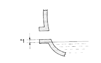
Обозначения на рисунке *1 0 - 5 мм (0 - 0,20 дюйма) Убедитесь в том, что поверхность масла попадает в зону 5 мм (0,20 дюйма) нижней части наливного отверстия механической трансмиссии.
Note
Чрезмерно большое или малое количество масла может приводить к возникновению неисправностей.
-
Если уровень масла мал, проверьте, нет ли утечек.
-
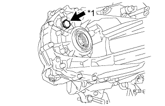
Обозначения на рисунке *1 Пробка наливного отверстия Установите на место пробку наливного отверстия механической трансмиссии и новую прокладку.
- Torque:
- 39 Н*м { 400 кгс*см, 29 фунт-сила-дюймов }
-
-
INSPECT FOR ENGINE OIL LEAK
-
INSPECT FOR EXHAUST GAS LEAK
-
INSPECT FOR FUEL LEAK
-
INSPECT IGNITION TIMING
Note
-
Turn all the electrical systems and the air conditioning off.
-
Inspect the ignition timing with the cooling fan off.
-
When checking the ignition timing, shift the transmission to the neutral position.
-
When using the intelligent tester:
-
Warm up and stop the engine.
-
Connect the intelligent tester to the DLC3.
-
Turn the ignition switch to ON.
-
Enter the following menus: Powertrain / Engine and ECT / Active Test / TE1 (TC) / ON.
Tech Tips
Refer to the intelligent tester operator's manual for further information regarding the selection of Active Test.
-
Inspect the ignition timing during idling.
Ignition timing 8 to 12° BTDC -
Enter the following menus: Powertrain / Engine and ECT / Active Test / TE1 (TC) / OFF.
-
Turn the ignition switch off.
-
Disconnect the intelligent tester from the DLC3.
-
-
When not using the intelligent tester:
-
Remove the No. 3 engine under cover Click here.
-
Remove the No. 1 engine cover Click here.
-
Warm up and stop the engine.
-
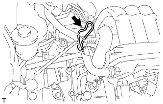
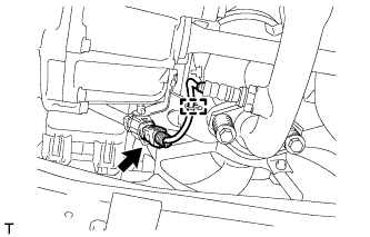
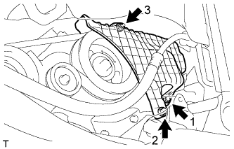
Install the tester terminal of a timing light onto the position shown in the illustration.
Note
-
Use a timing light that detects the first signal.
-
Wrap the wire harness with tape after checking.
-
-
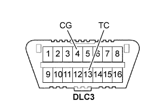
Using SST, connect terminals 13 (TC) and 4 (CG) of the DLC3.
- SST
- 09843-18040
Note
Check the terminal numbers before connecting them. Connecting the wrong terminals could damage the engine.
-
Turn the ignition switch to ON.
-
Inspect the ignition timing during idling.
Ignition timing 8 to 12° BTDC Tech Tips
Run the engine speed at 1000 to 1300 rpm for 5 seconds and then check that the engine speed returns to the idling speed.
-
Disconnect terminals 13 (TC) and 4 (CG) of the DLC3.
-
Turn the ignition switch off.
-
Remove the timing light.
-
Install the No. 1 engine cover Click here.
-
Install the No. 3 engine under cover Click here.
-
-
-
INSPECT ENGINE IDLING SPEED
Note
-
Turn all the electrical systems and the air conditioning off.
-
Inspect the engine idling speed with the cooling fan off.
-
When checking the idling speed, shift the transmission to the neutral position.
-
Warm up and stop the engine.
-
When using the intelligent tester:
-
Connect the intelligent tester to the DLC3.
-
Turn the ignition switch to ON.
-
Enter the following menus: Powertrain / Engine and ECT / Data List / Engine SPD.
Tech Tips
Refer to the intelligent tester operator's manual for further information regarding the selection of Data List.
-
Inspect the engine idling speed.
Idling speed 650 to 800 rpm -
Turn the ignition switch off.
-
Disconnect the intelligent tester from the DLC3.
-
-
When not using an intelligent tester:
-
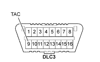
Install SST to terminal 9 (TAC) of the DLC3, and then connect a tachometer.
- SST
- 09843-18040
Note
Check the terminal numbers before connecting them. Connecting the wrong terminals could damage the engine.
-
Turn the ignition switch to ON.
-
Inspect the engine idling speed.
Idling speed 650 to 800 rpm -
Turn the ignition switch off.
-
Disconnect the tachometer.
-
Remove SST from terminal 9 (TAC).
-
-
-
INSPECT CO/HC
Tech Tips
The ECM controls the concentration of CO/HC in the emission gas.
-
Start the engine.
-
Run the engine at 2500 rpm for approximately 180 seconds.
-
Insert the CO/HC meter testing probe at least 40 cm (1.3 ft) into the tailpipe during idling.
-
Check the CO/HC concentration during idling and when running at 2500 rpm.
Standard CO concentration 0.2 % or less HC concentration 70 ppm or less If the CO/HC concentration does not comply with the regulations, troubleshoot in the order given below.
-
Check the heated oxygen sensor operation Click here.
-
See the table below for possible causes, and then inspect the applicable parts and repair them if necessary.
CO HC Problem Cause Normal High Rough idling
-
Faulty ignition:
-
Fouled, shorted or improperly gapped plugs
-
Incorrect valve clearance
-
Leakage from intake and exhaust valves
-
Leakage from cylinders
Low High Rough idling
(Fluctuating HC reading)
-
Lean mixture causing misfire
-
Faulty SFI systems:
-
Faulty pressure regulator
-
Faulty engine coolant temperature sensor
-
Faulty mass air flow meter
-
Faulty ECM
-
Faulty injectors
-
Faulty throttle body
High High Rough idling
(Black smoke from exhaust)
-
Faulty SFI systems:
-
Faulty pressure regulator
-
Faulty engine coolant temperature sensor
-
Faulty mass air flow meter
-
Faulty ECM
-
Faulty injectors
-
Faulty throttle body
-
-
-
INSPECT AND ADJUST FRONT WHEEL ALIGNMENT
-
INSTALL NO. 1 ENGINE COVER
-
Temporarily install the No. 1 engine cover with the 2 bolts and nut.
-
Fully tighten the 2 bolts and nut in the order shown in the illustration.
- Torque:
- 10 N*m { 102 kgf*cm, 7 ft.*lbf }
-
-
INSTALL NO. 1 COOLER COVER
-
Temporarily install the No. 1 cooler cover with the 2 nuts.
-
Fully tighten the 2 nuts in the order shown in the illustration.
- Torque:
- 9.8 N*m { 100 kgf*cm, 87 in.*lbf }
-
-
INSTALL NO. 3 ENGINE UNDER COVER
-
Install the No. 3 engine under cover with the 3 clips.
-
-
INSTALL NO. 1 ENGINE UNDER COVER
-
INSTALL NO. 2 ENGINE UNDER COVER
-
INSTALL FRONT FLOOR COVER RH
-
INSTALL FRONT FLOOR COVER LH
-
INSTALL WINDSHIELD WIPER MOTOR AND LINK