ПЕРЕДНИЙ САЛЬНИК КОЛЕНЧАТОГО ВАЛА УСТАНОВКА

-
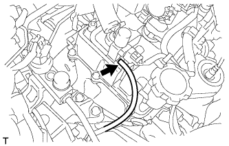
INSTALL TIMING CHAIN COVER OIL SEAL
-
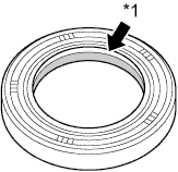
Apply MP grease to the lip of a new oil seal.
Text in Illustration *1 MP Grease Note
Keep the lip free of foreign matter.
-
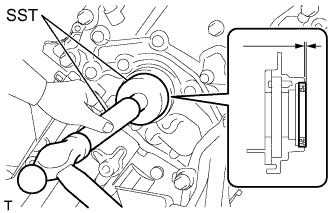
Using SST and a hammer, tap in the oil seal as shown in the illustration.
- SST
- 09950-60010 ( 09951-00500, 09952-06010 )
- 09950-70010 ( 09951-00720 )
Standard depth -1.0 to 0.5 mm (-0.0394 to 0.0197 in.) Note
-
Wipe off extra grease from the crankshaft.
-
Do not tap the oil seal at an angle.
-
-
INSTALL CRANKSHAFT PULLEY
-
Align the pulley set key with the key groove of the pulley.
-
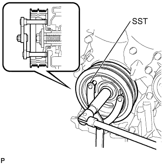
Using SST, hold the pulley in place and tighten the bolt.
- SST
- 09960-10010 ( 09962-01000, 09963-01000 )
- Torque:
- 180 N*m { 1835 kgf*cm, 133 ft.*lbf }
-
-
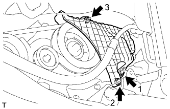
INSTALL ENGINE MOUNTING INSULATOR SUB-ASSEMBLY RH
-
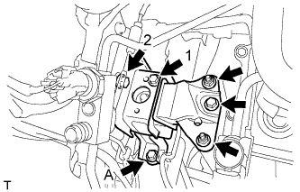
Temporarily tighten the bolt A.
-
Tighten the 2 bolts on the vehicle side in the sequence shown in the illustration.
- Torque:
- 52 N*m { 530 kgf*cm, 38 ft.*lbf }
-
Fully tighten the bolt A.
- Torque:
- 52 N*m { 530 kgf*cm, 38 ft.*lbf }
-
Tighten the bolt and 2 nuts on the engine side and install the engine mounting insulator RH.
-
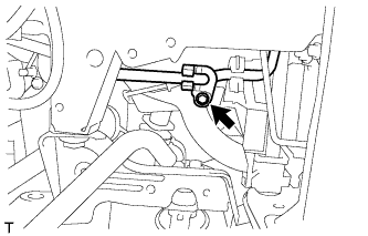
Connect the vacuum hose to the vacuum switching valve assembly.
-
-
CONNECT DISCHARGE HOSE SUB-ASSEMBLY
-
Apply sufficient compressor oil to a new O-ring and the fitting surface of the tube joint.
Compressor oil ND-OIL8 or equivalent -
Install the O-ring onto the discharge hose.
-
Connect the discharge hose sub-assembly with the bolt.
- Torque:
- 5.0 N*m { 55 kgf*cm, 44 in.*lbf }
-
-
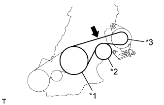
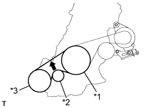
INSTALL FAN AND GENERATOR V BELT
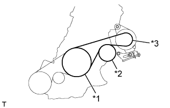
Text in Illustration *1 Crankshaft Pulley *2 Water Pump Assembly *3 Generator Assembly
-
Temporarily install the V-ribbed belt onto each pulley.
Note
-
Before installing the V-ribbed belt, check each pulley for any kind of liquid and chips.
-
Check that the ribs of the V-ribbed belt are correctly fitted into the grooves of the pulleys.
-
-
-
ADJUST FAN AND GENERATOR V BELT
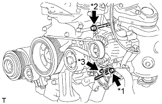
Text in Illustration *1 Bolt B *2 Bolt A *3 Bolt C
-
Turn the bolt B to adjust the tension of the V-ribbed belt.
-
Tighten fixing bolts A and C.
- Torque:
- Bolt A
- 54 N*m { 551 kgf*cm, 40 ft.*lbf }
- Bolt C
- 21 N*m { 214 kgf*cm, 15 ft.*lbf }
-
-
INSPECT FAN AND GENERATOR V BELT
-
Text in Illustration *1 Crankshaft Pulley *2 Water Pump Pulley *3 Generator Pulley 
Specified Point Check the fan and generator V-ribbed belt deflection (when inspecting a vehicle w/o No. 1 engine cover, or without the No. 1 engine cover installed).
Deflection Pressing Force
N (kg, Ib)
New Belt
mm (in.)
Used Belt
mm (in.)
10
(10, 22)
8.0 to 10.5
(0.315 to 0.413)
11.0 to 14.0
(0.433 to 0.551)
Note
-
Check the belt deflection between the pulleys at the indicated measurement point (directly between the pulleys).
-
When installing a new belt, set its deflection value as specified.
-
When checking a belt used for over 5 minutes, confirm that the deflection value is within the specified range for a used belt.
-
When reinstalling a belt used for over 5 minutes, check whether its deflection value is within the specified range for a used belt.
-
-
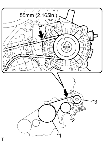
Text in Illustration *1 Crankshaft Pulley *2 Water Pump Pulley *3 Generator Pulley Specified Point Check the fan and generator V-ribbed belt deflection (when inspecting a vehicle while the No. 1 engine cover is installed).
Deflection Pressing Force
N (kg, Ib)
New Belt
mm (in.)
Used Belt
mm (in.)
10
(10, 22)
4.5 to 6.0
(0.177 to 0.236)
6.5 to 7.5
(0.256 to 0.295)
Note
-
Check the belt deflection between the pulleys at the indicated measurement point (on the left side of the generator pulley, 55 mm (2.165 in.) from the center of the pulley).
-
When installing a new belt, set its deflection value as specified.
-
When checking a belt used for over 5 minutes, confirm that the deflection value is within the specified range for a used belt.
-
When reinstalling a belt used for over 5 minutes, check whether its deflection value is within the specified range for a used belt.
-
-
-
INSTALL NO. 1 V (COOLER COMPRESSOR TO CRANKSHAFT PULLEY) BELT
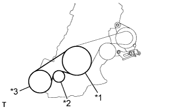
Text in Illustration *1 Crankshaft Pulley *2 Idler Pulley *3 Cooler Compressor Assembly
-
Temporarily install the V-ribbed belt onto each pulley.
Note
-
Before installing the V-ribbed belt, check each pulley for any kind of liquid and chips.
-
Check that the ribs of the V-ribbed belt are correctly fitted into the grooves of the pulleys.
-
-
-
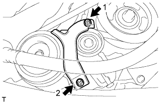
ADJUST NO. 1 V (COOLER COMPRESSOR TO CRANKSHAFT PULLEY) BELT
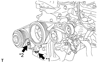
Text in Illustration *1 Bolt B *2 Bolt A
-
Turn the bolt B to adjust the tension of the V-ribbed belt.
-
Tighten bolt A.
-
-
INSPECT NO. 1 V (COOLER COMPRESSOR TO CRANKSHAFT PULLEY) BELT
-
Text in Illustration *1 Crankshaft Pulley *2 Idler Pulley *3 Cooler Compressor Assembly Specified Point Check the No. 1 (cooler compressor to crankshaft pulley) belt.
Deflection Pressing Force
N (kg, Ib)
New Belt
mm (in.)
Used Belt
mm (in.)
10
(10, 22)
8.0 to 10.0
(0.315 to 0.394)
11.0 to 14.0
(0.433 to 0.551)
Note
-
Check the No. 1 (cooler compressor to crankshaft pulley) belt deflection at the specified point.
-
When installing a new belt, set its deflection value as specified.
-
When checking a belt used for over 5 minutes, confirm that the deflection value is within the specified range for a used belt.
-
When reinstalling a belt used for over 5 minutes, check whether its deflection value is within the specified range for a used belt.
-
-
-
ADD ENGINE OIL
-
Add new engine oil and install the oil filler cap.
Engine Oil Oil Grade Oil Viscosity (SAE)
-
API grade SL or SM multigrade engine oil
-
20W-50
-
15W-40
-
API grade SL "Energy-Conserving" "Energy-Conserving SM or ILSAC multigrade engine oil"
-
10W-30
-
5W-30
-
5W-20
-
0W-20
Capacity Item Standard Condition Drain and refill with oil filter change 3.1 liters (3.3 US qts, 2.7 Imp. qts) Drain and refill without oil filter change 2.9 liters (3.1 US qts, 2.6 Imp. qts) Dry fill 3.4 liters (3.6 US qts, 3.0 Imp. qts) -
-
-
INSPECT FOR ENGINE OIL LEAK
-
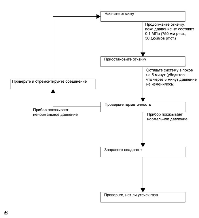
CHARGE REFRIGERANT
Tech Tips
Заправляйте хладагент в соответствии с руководством на оборудование.
-
Используя вакуумный насос, выполните вакуумную очистку.
-
Заправьте хладагент HFC-134a (R134a).
- SST
- 09985-20010 ( 09985-02010, 09985-02050, 09985-02060, 09985-02070, 09985-02080, 09985-02090, 09985-02110, 09985-02130, 09985-02140, 09985-02150 )
Номинальное значение 330 - 390 г (11,6 - 13,8 унции) Note
-
Не запускайте двигатель до заправки хладагента, поскольку компрессор системы кондиционирования не сможет нормально работать при нехватке хладагента. В результате возможен перегрев компрессора.
-
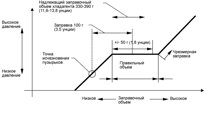
После исчезновения пузырьков может потребоваться заправить примерно 100 г (3,5 унции) хладагента.
Количество хладагента следует измерять, а не проверять через смотровое окно.
Tech Tips
-
Ниже описана взаимосвязь между заправочным объемом хладагента и давлением.
-
При чрезмерном объеме хладагента:
При чрезмерной заправке системы хладагентом увеличивается давление со стороны высокого давления. Начинают часто возникать отсечки высокого давления. Как следствие, снижается холодопроизводительность, и смазывание компрессора оказывается недостаточным.
-
При малом объеме хладагента:
Нехватка хладагента приводит к низкой эффективности системы охлаждения и плохой циркуляции масла, вследствие чего сокращается срок службы компрессора. Работа при недостаточном количестве хладагента сопровождается увеличением температуры хладагента, что вызывает тепловое разрушение резиновых шлангов и уплотнений. В результате могут появляться трещины с последующей утечкой хладагента.
-
Установите крышки на рабочие клапаны линии подачи хладагента.
-
-
WARM UP ENGINE
Note
После заправки хладагента в течение, по крайней мере, 1 мин. прогрейте двигатель при частоте вращения 2000 об/мин.
-
INSPECT REFRIGERANT LEAK
-
После заправки газообразного хладагента с помощью галогенного течеискателя проверьте, нет ли утечек хладагента.
-
Выполните описанные ниже действия:
-
Выключите двигатель.
-
Обеспечьте хорошую вентиляцию (галогенный течеискатель может реагировать на летучие газы, не являющиеся хладагентом - такие, как пары бензина и отработавшие газы).
-
Испытание необходимо выполнить 2 или 3 раза.
-
Убедитесь в том, что в системе охлаждения осталось некоторое количество хладагента.
Показания при выключенном компрессоре: приблизительно 392–588 кПа (4–6 кгс/см2, 57–85 фунтов на кв. дюйм)
Tech Tips
При наличии утечки указанное давление поддерживать невозможно.
-
-
С помощью галоидного течеискателя проверьте трубопроводы подачи хладагента, особенно в местах соединений, на наличие утечки.
-
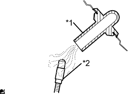
Обозначения на рисунке *1 Сливной шланг *2 Галогенный течеискатель Прежде чем приступить к испытанию, расположите галоидный течеискатель рядом со сливным шлангом.
Tech Tips
-
После остановки электродвигателя вентилятора дайте блоку охлаждения охладиться в течение не менее 15 минут.
-
Разместите датчик галоидного течеискателя под сливным шлангом.
-
Расположив галогенный течеискатель рядом со сливным шлангом, убедитесь, что он не реагирует на прочие летучие газы.
Если такой реакции избежать не удается, автомобиль необходимо поднять.
-
-
Если в сливном шланге утечка газа не обнаруживается, снимите электродвигатель вентилятора с блока охлаждения. Вставьте датчик галогенного течеискателя в блок и выполните испытание.
-
Отсоедините разъем контактного датчика давления и оставьте его в таком состоянии приблизительно на 20 мин. Поднесите галогенный течеискатель к контактному датчику давления и выполните испытание.
-
-
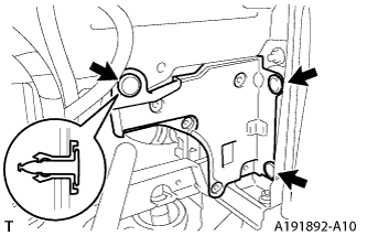
INSTALL NO. 1 ENGINE COVER (w/ No. 1 Engine Cover)
-
Temporarily install the No. 1 engine cover with the 2 bolts and nut.
-
Fully tighten the 2 bolts and nut in the order shown in the illustration.
- Torque:
- 10 N*m { 102 kgf*cm, 7 ft.*lbf }
-
-
INSTALL NO. 1 COOLER COVER (w/ No. 1 Cooler Cover)
-
Temporarily install the No. 1 cooler cover with the 2 nuts.
-
Fully tighten the 2 nuts in the order shown in the illustration.
- Torque:
- 9.8 N*m { 100 kgf*cm, 87 in.*lbf }
-
-
INSTALL ENGINE UNDER COVER RH
-
INSTALL NO. 3 ENGINE UNDER COVER
-
Install the No. 3 engine under cover with the 3 clips.
-