ПЕРЕДНИЙ САЛЬНИК КОЛЕНЧАТОГО ВАЛА СНЯТИЕ

-
REFRIGERANT FROM REFRIGERATION SYSTEM
-
Запустите двигатель.
-
Включите систему кондиционирования.
-
Включите вентилятор.
-
Включите компрессор системы кондиционирования при частоте вращения коленчатого вала двигателя около 1000 об/мин на 5-6 мин., чтобы прокачать хладагент и собрать оставшееся в компонентах компрессорное масло в компрессоре.
-
Выключите двигатель.
-
Снимите крышки с рабочих клапанов на линии подачи хладагента.
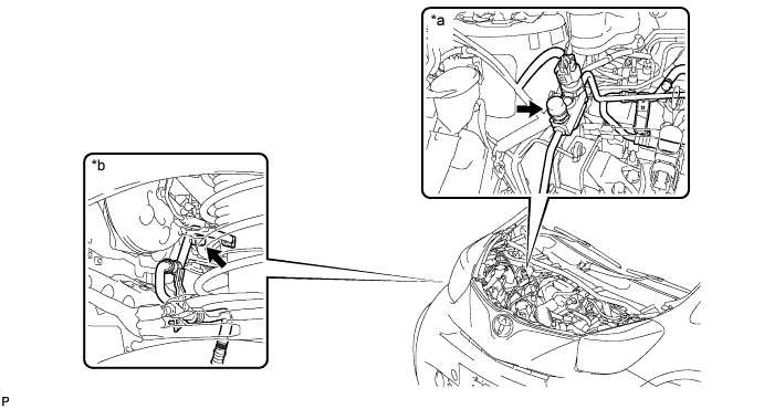
Обозначения на рисунке *a Со стороны моторного отсека *b Со стороны колесной арки Доступ к части системы с высоким давлением Тип двигателя Для моделей с правосторонним рулевым управлением Для моделей с левосторонним рулевым управлением 1KR-FE Моторный отсек Моторный отсек 1NR-FE Моторный отсек Моторный отсек 1ND-TV Моторный отсек Моторный отсек Доступ к части системы с низким давлением Тип двигателя Для моделей с правосторонним рулевым управлением Для моделей с левосторонним рулевым управлением 1KR-FE Колесная арка Колесная арка 1NR-FE Колесная арка Колесная арка 1ND-TV Колесная арка Колесная арка -
Подсоедините установку регенерации хладагента.
-
Соберите хладагент из системы кондиционирования с помощью установки регенерации хладагента.
Tech Tips
Устройство сбора/регенерации хладагента следует использовать в соответствии с руководством по эксплуатации изготовителя.
-
-
REMOVE NO. 3 ENGINE UNDER COVER
-
Remove the 3 clips and No. 3 engine under cover.
-
-
REMOVE ENGINE UNDER COVER RH
-
REMOVE NO. 1 COOLER COVER
-
Remove the 2 nuts and the No. 1 cooler cover.
-
-
REMOVE NO. 1 ENGINE COVER
-
Remove the 2 bolts, nut and the No. 1 engine cover.
-
-
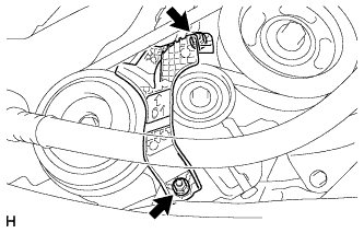
REMOVE NO. 1 V (COOLER COMPRESSOR TO CRANKSHAFT PULLEY) BELT
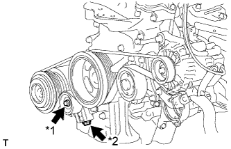
Text in Illustration *1 Bolt A *2 Adjusting Bolt B
-
Loosen the bolt A.
-
Turn adjusting bolt B to release the tension and remove the V belt from the pulleys.
-
-
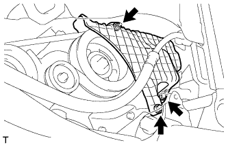
REMOVE FAN AND GENERATOR V BELT
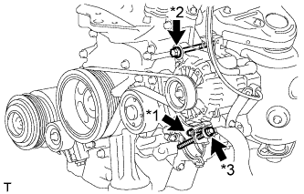
Text in Illustration *1 Bolt A *2 Bolt B *3 Bolt C
-
Loosen the bolt A and B.
-
Turn adjusting bolt C to release the tension and remove the V belt from the pulleys.
-
-
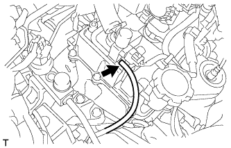
DISCONNECT DISCHARGE HOSE SUB-ASSEMBLY
-
Remove the bolt and disconnect the discharge hose sub-assembly.
-
Remove the O-ring from the discharge hose sub-assembly.
Tech Tips
Seal the openings of the disconnected parts using vinyl tape to prevent the entry of moisture and foreign matter.
-
-
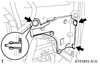
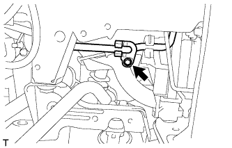
REMOVE ENGINE MOUNTING INSULATOR SUB-ASSEMBLY RH
-
Disconnect the vacuum hose from the vacuum switching valve assembly.
-
Place a wooden block between a floor jack and the engine, and then support the engine using the floor jack.
-
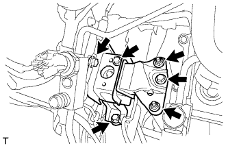
Remove the 4 bolts, 2 nuts and engine mounting insulator sub-assembly RH.
-
-
REMOVE CRANKSHAFT PULLEY
-
Operate the jack and slowly lower the engine.
Note
Do not lower the engine more than necessary.
-
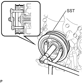
Using SST, hold the pulley in place and loosen the pulley bolt.
- SST
- 09960-10010 ( 09962-01000, 09963-01000 )
-
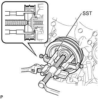
Using SST, remove the crankshaft pulley and pulley bolt.
- SST
- 09950-40011 ( 09951-04010, 09953-04030, 09958-04011, 09955-04011, 09954-04010, 09952-04010 )
-
-
REMOVE TIMING CHAIN COVER OIL SEAL
-
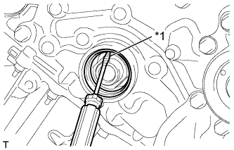
Text in Illustration *1 Protective Tape Using a knife, cut off the lip of the oil seal.
-
Using a screwdriver with its tip wrapped in protective tape, pry out the oil seal.
Note
After removing, check the crankshaft for damage. If damaged, smooth the surface with 400-grit sandpaper.
-