БЛОК ЦИЛИНДРОВ ПОВТОРНАЯ СБОРКА

-
INSTALL CRANKSHAFT BEARING
-
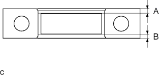
Align the crankshaft lower bearing with the bearing cap and install the crankshaft bearing cap.
Note
-
Install the bearing cap so that the gap between A and B is less than 0.8 mm (0.031 in.)
-
Do not apply engine oil to the bearing and its contact surface.
-
-

Align the crankshaft bearing (upper) with the oil hole in of the cylinder block and install the bearing.
Note
Do not apply engine oil to the bearing or its contact surface.
-
-
INSTALL CRANKSHAFT THRUST WASHER UPPER
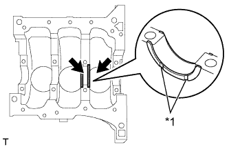
Text in Illustration *1 Oil Groove
-
Apply engine oil to the oil groove.
-
Install the 2 crankshaft thrust washers onto the No. 3 journal position of the cylinder block with the oil grooves facing outward.
-
-
INSTALL CRANKSHAFT
-
Apply engine oil to the sliding surface of the crankshaft bearing (upper) and install the crankshaft.
-
Apply engine oil to the sliding surface of the crankshaft bearing (lower) and install the crankshaft bearing cap with the front mark facing forward.
-
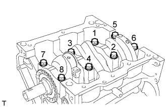
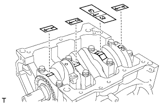
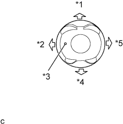
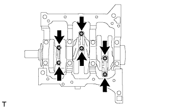
Apply engine oil to the crankshaft bolts and install them in 2 or 3 steps, in the order shown in the illustration.
- Torque:
- 59 N*m { 602 kgf*cm, 44 ft.*lbf }
-
Make sure that the crankshaft turns smoothly.
-
-
INSTALL WITH PIN PISTON SUB-ASSEMBLY
-
Gradually heat the piston up to 80 to 90°C (176 to 194°F).
-
Apply engine oil to the smaller end of a new connecting rod and a new piston pin.
-
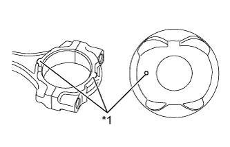
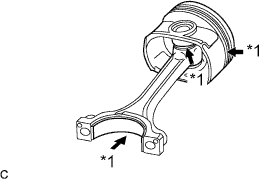
Text in Illustration *1 Front Mark Align the front marks on the piston with the connecting rod and assemble them.
-
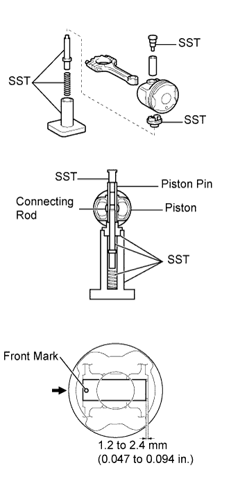
Using SST and a press, press in the piston pin.
- SST
- 09221-25026 ( 09221-00021, 09221-00030, 09221-00130, 09221-00141, 09221-00150 )
Note
-
Press the piston pin in from the front mark side of the piston.
-
Do not press the piston pin in at an angle.
-
Hold the connecting rod and check that the piston moves smoothly.
-
-
INSTALL PISTON RING SET
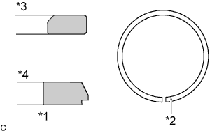
Text in Illustration *1 Compression Ring *2 Identification Mark (T) *3 No. 1 *4 No. 2
-
Install the oil ring.
-
Using a piston ring expander, install the No. 2 compression ring and No. 1 compression ring with the identification marks (T) facing upward.
-
Text in Illustration *1 Oil Ring (Side Rail) *2 No. 1 Compression Ring *3 Front Mark *4 Oil Ring (Expander) *5 No. 2 Compression Ring Install the rings so that each end faces as shown in the illustration.
-
-
INSTALL CONNECTING ROD BEARING
-
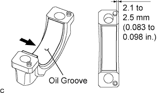
Align the connecting rod bearing oil groove of the connecting rod cap.
-
Install the connecting rod bearing onto the connecting rod bearing cap, as shown in the illustration.
Note
Do not apply engine oil to the bearing or its contact surface.
-
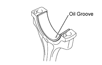
Align the connecting rod bearing oil groove of the connecting rod.
-
Install the connecting rod bearing onto the connecting rod.
Note
Do not apply engine oil to the bearing or its contact surface.
-
-
INSTALL CONNECTING ROD SUB-ASSEMBLY
-
Make sure that the compression rings and oil ring are installed in the correct directions.
Text in Illustration *1 Oil Ring (Side Rail) *2 No. 1 Compression Ring *3 Front Mark *4 Oil Ring (Expander) *5 No. 2 Compression Ring -
Text in Illustration *1 Apply Engine Oil. Apply engine oil to the sliding surfaces of the piston and connecting rod sub-assembly.
-
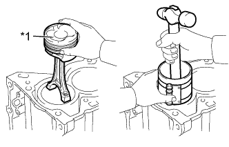
Text in Illustration *1 Front Mark Using a piston ring compressor, push the numbered piston and connecting rod assemblies into each cylinder with the front mark of the piston facing forward.
-
Text in Illustration *1 Apply Engine Oil. Apply engine oil to the sliding surface of the connecting rod bearing.
-
Text in Illustration *1 Front Mark Install the connecting rod with the front mark of the connecting rod bearing cap facing forward.
Note
-
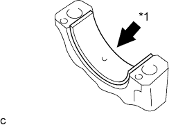
Install the connecting rod bearing cap with the front mark facing forward. Make sure that the knock pin aligns with the knock pin hole.
-
Do not change the connecting rod and connecting rod bearing cap combination.
-
-
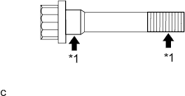
Text in Illustration *1 Apply Engine Oil. Apply a light coat of engine oil to the seating position and threads of the connecting rod bolt.
-
Alternately tighten the connecting rod bolts in 2 or 3 steps.
- Torque:
- 15 N*m { 153 kgf*cm, 11 ft.*lbf }
-
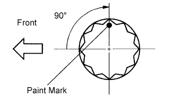
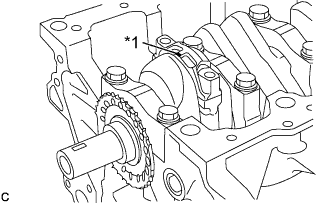
Mark the front of the connecting cap bolts with paint.
-
Retighten the cap bolts by an additional 90° as shown in the illustration.
-
Check that the crankshaft turns smoothly.
-
-
INSTALL CYLINDER BLOCK WATER JACKET SPACER (w/ Cylinder Block Water Jacket Spacer)
-
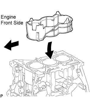
Install the cylinder block water jacket spacer to the cylinder head.
Note
Make sure that the top edge of the cylinder block water jacket spacer is below the top of the cylinder block.
-