ЗАЗОР В ПРИВОДЕ КЛАПАНОВ РЕГУЛИРОВКА
-
REMOVE NO. 3 ENGINE UNDER COVER (w/ No. 1 Engine Cover)
-
Снимите 3 фиксатора и защиту картера двигателя № 3.
-
-
REMOVE NO. 1 ENGINE COVER (w/ No. 1 Engine Cover)
-
Remove the 2 bolts, nut and the No. 1 engine cover.
-
-
REMOVE INTAKE MANIFOLD
-
Remove the intake manifold Click here.
-
-
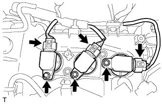
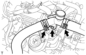
REMOVE NO. 1 IGNITION COIL
-
Disconnect the 3 No. 1 ignition coil connectors.
-
Remove the 3 bolts and the 3 No. 1 ignition coils.
-
-
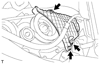
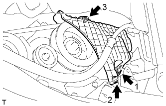
REMOVE RADIATOR RESERVOIR TANK HOSE
-
Отсоедините шланг расширительного бачка радиатора от хомута шланга.
-
Ослабьте фиксатор и отсоедините шланг расширительного бачка радиатора.
-
-
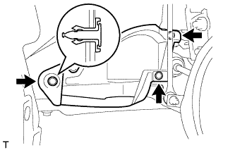
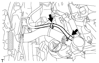
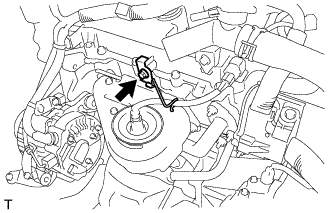
REMOVE WATER FILLER ASSEMBLY
-
Loosen the 2 clips and disconnect the No. 1 radiator hose and No. 3 radiator hose.
-
Remove the bolt and the water filler assembly.
-
-
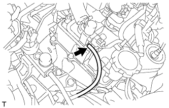
REMOVE HARNESS BRACKET
-
Remove the bolt and the harness bracket.
-
-
REMOVE CYLINDER HEAD COVER SUB-ASSEMBLY
-
Disconnect the vacuum hose from the vacuum switching valve.
-
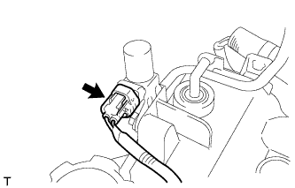
Disconnect the vacuum switching valve connector.
-
Separate the wire harness from the cylinder head cover sub-assembly
-
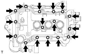
Remove the 16 bolts and the cylinder head cover sub-assembly.
-
Remove the gasket from the cylinder head cover sub-assembly.
-
-
SET NO. 1 CYLINDER TO TDC/COMPRESSION
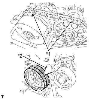
Text in Illustration *1 Timing Mark *2 Timing Pointer
-
Turn the crankshaft pulley clockwise to align the timing mark on the pulley with the timing pointer of the timing chain cover.
-
Make sure that the timing mark of the camshaft sprocket is at the top.
Tech Tips
If the matchmarks do not align, turn the crankshaft clockwise one complete revolution and then check that they align.
-
-
INSPECT VALVE CLEARANCE
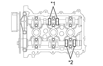
Text in Illustration *1 Intake Side *2 Exhaust Side
-
Check only the valves indicated.
-
Using a feeler gauge, measure the clearance between the valve lifter and camshaft.
Valve clearance (Cold) Intake side 0.145 to 0.235 mm (0.00571 to 0.00925 in.) Exhaust side 0.275 to 0.365 mm (0.01083 to 0.01437 in.) Tech Tips
Insert the feeler gauge from the spark plug side (center).
-
Record any out-of-specification valve clearance measurements. They will be used later to determine the required replacement valve lifters.
-
-
Turn the crankshaft 1 revolution (360°).
-
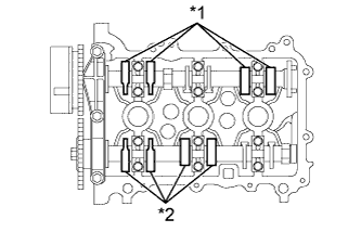
Text in Illustration *1 Intake Side *2 Exhaust Side Check only the valves indicated.
-
Using a feeler gauge, measure the clearance between the valve lifter and camshaft.
Valve clearance (Cold) Intake side 0.145 to 0.235 mm (0.00571 to 0.00925 in.) Exhaust side 0.275 to 0.365 mm (0.01083 to 0.01437 in.) Tech Tips
Insert the feeler gauge from the spark plug side (center).
-
Record any out-of-specification valve clearance measurements. They will be used later to determine the required replacement valve lifters.
-
-
-
ADJUST VALVE CLEARANCE
-
Remove the No. 1 and No. 2 camshafts Click here.
-
Remove the valve lifters Click here.
-
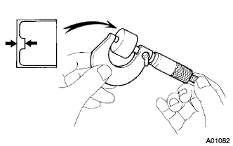
Using a micrometer, measure the thickness of the removed valve lifters.
-
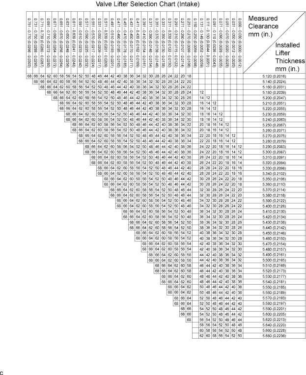
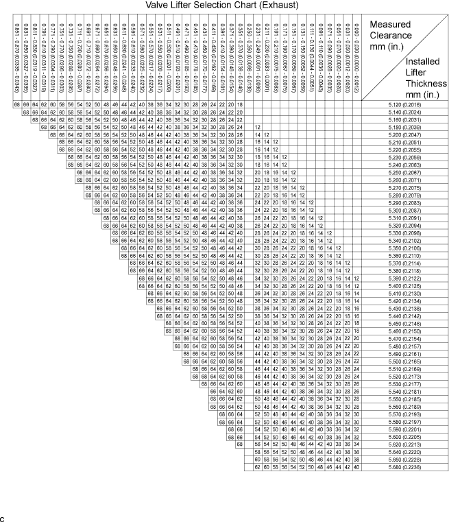
Calculate the thickness of a new lifter so that the valve clearance comes within the specified value.
A Thickness of new lifter B Thickness of used lifter C Measured valve clearance Valve clearance Intake A = B + (C - 0.18 mm (0.0071 in.)) Exhaust A = B + (C - 0.31 mm (0.0122 in.)) Tech Tips
-
Select a new lifter with a thickness as close to the calculated values as possible.
-
Lifters are available in 29 sizes in increments of 0.020 mm (0.0008 in.), from 5.12 mm (0.2016 in.) to 5.68 mm (0.2236 in.).
-
Refer to the New Lifter Thickness Table on the next 2 pages.
-
-
Install the valve lifters Click here.
-
Install the No. 1 and No. 2 camshafts Click here.
Tech Tips
New Lifter Thickness mm (in.) Lifter No. Thickness Lifter No. Thickness Lifter No. Thickness 12 5.12 (0.2016) 32 5.32 (0.2094) 52 5.52 (0.2173) 14 5.14 (0.2024) 34 5.34 (0.2102) 54 5.54 (0.2181) 16 5.16 (0.2031) 36 5.36 (0.2110) 56 5.56 (0.2189) 18 5.18 (0.2039) 38 5.38 (0.2118) 58 5.58 (0.2197) 20 5.20 (0.2047) 40 5.40 (0.2126) 60 5.60 (0.2205) 22 5.22 (0.2055) 42 5.42 (0.2134) 62 5.62 (0.2213) 24 5.24 (0.2063) 44 5.44 (0.2142) 64 5.64 (0.2220) 26 5.26 (0.2071) 46 5.46 (0.2150) 66 5.66 (0.2228) 28 5.28 (0.2079) 48 5.48 (0.2157) 68 5.68 (0.2236) 30 5.30 (0.2087) 50 5.50 (0.2165) - -
-
-
INSTALL CYLINDER HEAD COVER SUB-ASSEMBLY
-
Clean the cylinder head cover, cylinder head assembly and timing chain cover assembly.
-
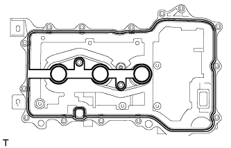
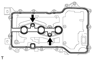
Fit the cylinder head cover gasket into the gasket groove on the cover and onto the center bosses.
-
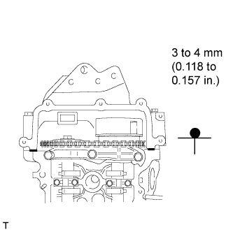
Apply a continuous bead of seal packing (diameter: 3 to 4 mm (0.118 to 0.157 in.)) to the contact surface between the cylinder head assembly and timing chain cover assembly, as shown in the illustration.
Seal packing Toyota Genuine Seal Packing Black, Three Bond 1207B or equivalent -
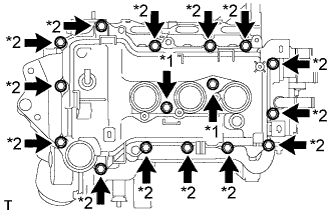
Text in Illustration *1 Bolt A *2 Bolt B Tighten the bolts A, and then the bolts B.
Note
After tightening all of the bolts, check that the bolts A meet the specified torque.
- Torque:
- 7.7 N*m { 79 kgf*cm, 68 in.*lbf }
-
Install the wire harness to the cylinder head cover sub-assembly.
-
Connect the vacuum switching valve connector.
-
Connect the vacuum hose to the vacuum switching valve.
-
-
INSTALL HARNESS BRACKET
-
Install the harness bracket with the bolt.
- Torque:
- 12 N*m { 122 kgf*cm, 9 ft.*lbf }
-
-
INSTALL WATER FILLER ASSEMBLY
-
Install the water filler assembly with the bolt.
- Torque:
- 13 N*m { 127 kgf*cm, 9 ft.*lbf }
-
Connect the No. 1 radiator hose and No. 3 radiator hose with the 2 clips.
-
-
INSTALL RADIATOR RESERVOIR TANK HOSE
-
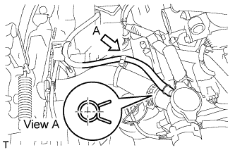
Connect the radiator reservoir tank hose with the clip.
Tech Tips
Install the clip as shown in the illustration.
-
-
INSTALL NO. 1 IGNITION COIL
-
Install the 3 No. 1 ignition coils with the 3 bolts.
- Torque:
- 9.0 N*m { 91 kgf*cm, 80 in.*lbf }
-
Connect the 3 No. 1 ignition coil connectors.
-
-
INSTALL INTAKE MANIFOLD
-
Install intake manifold Click here.
-
-
INSTALL NO. 1 ENGINE COVER (w/ No. 1 Engine Cover)
-
Temporarily install the No. 1 engine cover with the 2 bolts and nut.
-
Fully tighten the 2 bolts and nut in the order shown in the illustration.
- Torque:
- 10 N*m { 102 kgf*cm, 7 ft.*lbf }
-
-
INSTALL NO. 3 ENGINE UNDER COVER (w/ No. 1 Engine Cover)
-
Install the No. 3 engine under cover with the 3 clips.
-
-
CHECK FOR ENGINE OIL LEAKAGE