СИСТЕМА ECD Starter Signal Circuit
DESCRIPTION
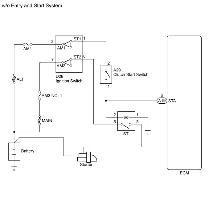
w/o Entry and Start System:
While the engine is being cranked, current flows from terminal ST1 of the ignition switch to the clutch start switch and also flows to terminal STA of the ECM (STA Signal).
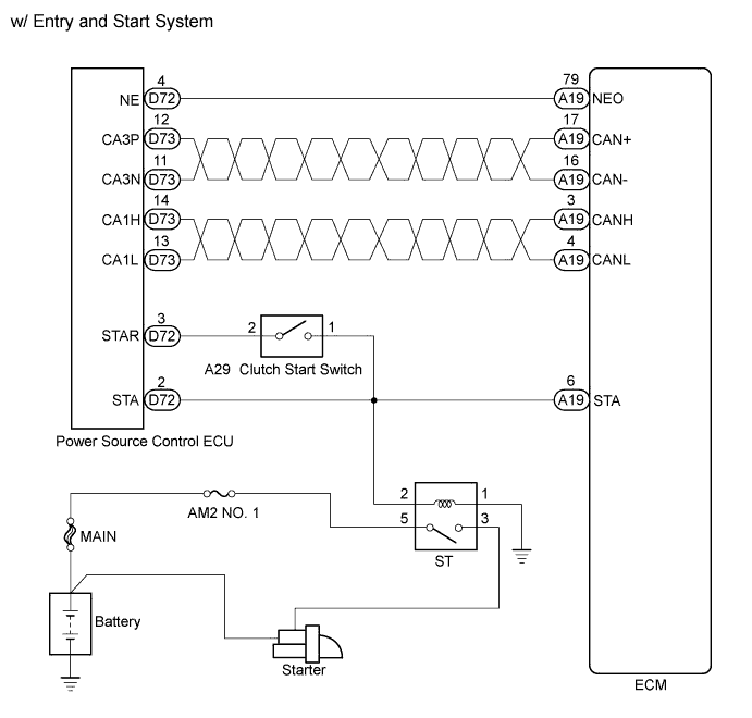
w/ Entry and Start System:
While the engine is being cranked, the ECM receives the STA signal from the power management ECU, and then the ECM performs starting based on its signal.
WIRING DIAGRAM
INSPECTION PROCEDURE
PROCEDURE
-
READ VALUE USING INTELLIGENT TESTER (STARTER SIGNAL)
-
Connect an intelligent tester to the DLC3.
-
Turn the ignition switch to ON and turn the tester on.
-
Enter the following menus: Powertrain / Engine and ECT / Data List / Starter Signal.
-
Check the result when the ignition switch is turned to ON and when the engine is started.
OK Ignition Switch Condition Display (Starter Signal) ON OFF Engine start ON Result Result Proceed to NG (w/ Entry and Start System) A NG (w/o Entry and Start System) B OK (w/ Entry and Start System) C OK (w/o Entry and Start System) D
B 
INSPECT CLUTCH START SWITCH ASSEMBLY Click here
C 
CHECK ENTRY AND START SYSTEM Click here
D
CHECK HARNESS AND CONNECTOR (CLUTCH START SWITCH - ECM - ST RELAY) Click here
A 
-
-
INSPECT CLUTCH START SWITCH ASSEMBLY (POWER SOURCE)
-
Remove the clutch start switch.
-
Measure the resistance according to the value(s) in the table below.
Standard Resistance Tester Connection Switch Condition Specified Condition 1 - 2 ON (Pushed) Below 1 Ω 1 - 2 OFF (Not pushed) 10 kΩ or higher -
Reinstall the clutch start switch.
NG
REPLACE CLUTCH START SWITCH ASSEMBLY Click here
OK
-
-
CHECK HARNESS AND CONNECTOR (CLUTCH START SWITCH - ECM)
-

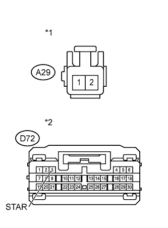
Text in Illustration *1 Front view of wire harness connector
(to Clutch Start Switch)
*2 Front view of wire harness connector
(to ECM)
Disconnect the clutch start switch connector.
-
Disconnect the ECM connector.
-
Measure the resistance according to the value(s) in the table below.
Standard Resistance (Check for Open) Tester Connection Condition Specified Condition A29-1 - A19-6 (STA) Always Below 1 Ω Standard Resistance (Check for Short) Tester Connection Condition Specified Condition A29-1 or A19-6 (STA) - Body ground Always 10 kΩ or higher -
Reconnect the clutch start switch connector.
-
Reconnect the ECM connector.
NG
REPAIR OR REPLACE HARNESS OR CONNECTOR
OK
-
-
CHECK HARNESS AND CONNECTOR (CLUTCH START SWITCH - POWER SOURCE CONTROL ECU)
-
Text in Illustration *1 Front view of wire harness connector
(to Clutch Start Switch)
*2 Front view of wire harness connector
(to Power Source Control ECU)
Disconnect the clutch start switch connector.
-
Disconnect the power source control ECU connector.
-
Measure the resistance according to the value(s) in the table below.
Standard Resistance (Check for Open) Tester Connection Condition Specified Condition A29-2 - D72-3 (STAR) Always Below 1 Ω Standard Resistance (Check for Short) Tester Connection Condition Specified Condition A29-2 or D72-3 (STAR) - Body ground Always 10 kΩ or higher -
Reconnect the clutch start switch connector.
-
Reconnect the power source control ECU connector.
NG
REPAIR OR REPLACE HARNESS OR CONNECTOR
OK 
CHECK ENTRY AND START SYSTEM Click here
-
-
INSPECT CLUTCH START SWITCH ASSEMBLY
-
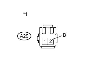
Text in Illustration *1 Front view of wire harness connector
(to Clutch Start Switch)
Disconnect the clutch start switch connector.
-
Measure the voltage according to the value(s) in the table below.
Standard Voltage Tester Connection Switch Condition Specified Condition A29-2 - Body ground Ignition switch START 11 to 14 V -
Reconnect the clutch start switch connector.
NG
INSPECT IGNITION SWITCH Click here
OK
-
-
INSPECT CLUTCH START SWITCH ASSEMBLY
-
Remove the clutch start switch.
-
Measure the resistance according to the value(s) in the table below.
Standard Resistance Tester Connection Switch Condition Specified Condition 1 - 2 ON (Pushed) Below 1 Ω 1 - 2 OFF (Not pushed) 10 kΩ or higher -
Reinstall the clutch start switch.
NG
REPLACE CLUTCH START SWITCH ASSEMBLY Click here
OK
-
-
CHECK HARNESS AND CONNECTOR (CLUTCH START SWITCH - ECM - ST RELAY)
-
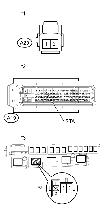
Text in Illustration *1 Front view of wire harness connector
(to Clutch Start Switch)
*2 Front view of wire harness connector
(to ECM)
*3 Engine Room Relay Block *4 ST Relay Disconnect the clutch start switch connector.
-
Remove the ST relay from the engine room relay block.
-
Disconnect the ECM connector.
-
Measure the resistance according to the value(s) in the table below.
Standard Resistance (Check for Open) Tester Connection Condition Specified Condition A29-1 - A19-6 (STA) Always Below 1 Ω A29-1 - 2 (ST relay) Always Below 1 Ω Standard Resistance (Check for Short) Tester Connection Condition Specified Condition A29-1 or A19-6 (STA) - Body ground Always 10 kΩ or higher A29-1 or 2 (ST relay) - Body ground Always 10 kΩ or higher -
Reconnect the clutch start switch connector.
-
Reconnect the ECM connector.
NG
REPAIR OR REPLACE HARNESS OR CONNECTOR
OK
REPLACE ECM Click here
-
-
INSPECT IGNITION SWITCH
-
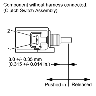
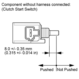
Text in Illustration *1 Component without harness connected
(Ignition Switch)
Remove the ignition switch.
-
Measure the resistance according to the value(s) in the table below.
Standard Resistance Tester Connection Switch Condition Specified Condition All terminals LOCK 10 kΩ or higher 2 - 3 ACC Below 1 Ω 2 - 3 - 4, 6 - 7 ON Below 1 Ω 1 - 2 - 4, 6 - 7 - 8 START Below 1 Ω -
Reinstall the ignition switch.
NG
REPLACE IGNITION SWITCH Click here
OK
-
-
CHECK HARNESS AND CONNECTOR (CLUTCH START SWITCH - IGNITION SWITCH - ST RELAY)
-
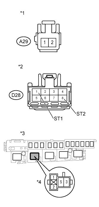
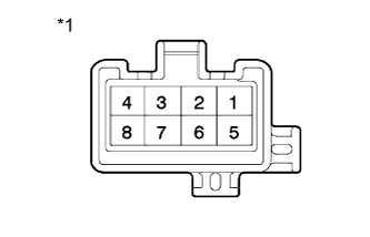
Text in Illustration *1 Front view of wire harness connector
(to Clutch Start Switch)
*2 Front view of wire harness connector
(to Ignition Switch)
*3 Engine Room Relay Block *4 ST Relay Remove the ST relay from the engine room relay block.
-
Disconnect the clutch start switch connector.
-
Disconnect the ignition switch connector.
-
Measure the resistance according to the value(s) in the table below.
Standard Resistance (Check for Open) Tester Connection Condition Specified Condition A29-2 - D28-1 (ST1) Always Below 1 Ω D28-8 (ST2) - 5 (ST relay) Always Below 1 Ω Standard Resistance (Check for Short) Tester Connection Condition Specified Condition A29-2 or D28-1 (ST1) - Body ground Always 10 kΩ or higher D28-8 (ST2) or 5 (ST relay) - Body ground Always 10 kΩ or higher -
Reconnect the clutch start switch connector.
-
Reconnect the ignition switch connector.
-
Reinstall the ignition switch.
NG
REPAIR OR REPLACE HARNESS OR CONNECTOR
OK
REPAIR OR REPLACE HARNESS OR CONNECTOR (IGNITION SWITCH - BATTERY)
-
-
CHECK HARNESS AND CONNECTOR (CLUTCH START SWITCH - ECM - ST RELAY)
-
Text in Illustration *1 Front view of wire harness connector
(to Clutch Start Switch)
*2 Front view of wire harness connector
(to ECM)
*3 Engine Room Relay Block *4 ST Relay Disconnect the clutch start switch connector.
-
Remove the ST relay from the engine room relay block.
-
Disconnect the ECM connector.
-
Measure the resistance according to the value(s) in the table below.
Standard Resistance (Check for Open) Tester Connection Condition Specified Condition A29-1 - A19-6 (STA) Always Below 1 Ω A29-1 - 2 (ST relay) Always Below 1 Ω Standard Resistance (Check for Short) Tester Connection Condition Specified Condition A29-1 or A19-6 (STA) - Body ground Always 10 kΩ or higher A29-1 or 2 (ST relay) - Body ground Always 10 kΩ or higher -
Reconnect the clutch start switch connector.
-
Reconnect the ECM connector.
NG
REPAIR OR REPLACE HARNESS OR CONNECTOR
OK
PROCEED TO NEXT SUSPECTED AREA SHOWN IN PROBLEM SYMPTOMS TABLE Click here
-