СИСТЕМА ECD, Diagnostic DTC:P1120
| DTC Code | DTC Name |
|---|---|
| P1120 | Accelerator Pedal Position Sensor Circuit Malfunction |
DESCRIPTION
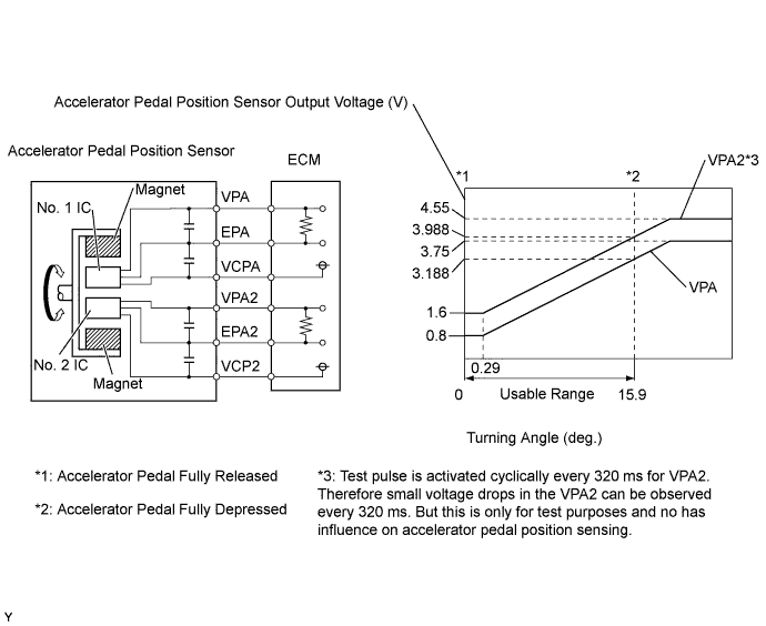
The Accelerator Pedal Position (APP) sensor is mounted on the accelerator pedal and detects the opening angle of the accelerator pedal. Since this sensor is electronically controlled with Hall-effect elements, accurate control and reliability can be obtained. It has 2 sensors to detect the accelerator position and malfunctions of the accelerator position sensor.
In the accelerator pedal position sensor, the voltage applied to pedal terminals VPA and VPA2 of the ECM changes between 0 V and 5 V in proportion to the opening angle of the accelerator pedal. The VPA is a signal which indicates the actual accelerator pedal opening angle and is used for engine control, and the VPA2 is a signal which indicates the information about the opening angle and is used for detecting malfunctions. The ECM judges the current opening angle of the accelerator pedal using signals from terminals VPA and VPA2, and the ECM controls the injection volume based on these signals.
| DTC Detection Drive Pattern | DTC Detection Condition | Trouble Area |
|---|---|---|
| Ignition switch is ON |
|
|
| DTC No. | Data List |
|---|---|
| P1120 |
|
Tech Tips
-
When DTC P1120 is stored, as a fail-safe operation the ECM limits engine power, such as by estimating the accelerator pedal position as 0 %.
-
When DTC P1120 is stored, check the accelerator pedal position sensor output by entering the following menus on the intelligent tester: Powertrain / Engine and ECT / Data List / Accel Position.
| Accelerator Pedal Position (Fully Closed) | Accelerator Pedal Position (Fully Open) | Trouble Area |
|---|---|---|
| 0% | 0% |
|
| Approximately 100% | Approximately 100% |
|
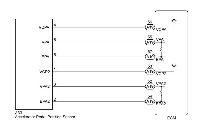
WIRING DIAGRAM
INSPECTION PROCEDURE
Note
When replacing the ECM, the ECM needs Registration and Initialization Click here.
Tech Tips
-
When the ECM must be replaced, before replacing the ECM, perform the "Learning Values Save" function using the intelligent tester. Then after installing the new ECM, perform all of the initializations/registrations for the "Learning Values Write" function by following the instructions shown on the tester display.
-
Read freeze frame data using the intelligent tester. Freeze frame data records the engine condition when malfunctions are detected. When troubleshooting, freeze frame data can help determine if the vehicle was moving or stationary, if the engine was warmed up or not, and other data from the time the malfunction occurred.
PROCEDURE
-
READ VALUE USING INTELLIGENT TESTER (ACCELERATOR PEDAL POSITION)
-
Connect the intelligent tester to the DLC3.
-
Turn the ignition switch to ON and turn the tester on.
-
Enter the following menus: Powertrain / Engine and ECT / Data List / Accel Sensor Out No.1 and Accel Sensor Out No.2.
-
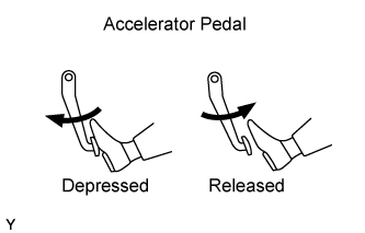
Read the value when depressing and releasing the accelerator pedal.
Standard Voltage Tester Display Condition Specified Condition
(Medium Value)
Accel Sensor Out No.1 Depressed Less than 4.6 V
(3.2 V)
Released More than 0.4 V
(0.7 V)
Accel Sensor Out No.2 Depressed Less than 4.6 V
(4.0 V)
Released More than 0.4 V
(1.5 V)
OK 
CONFIRM WHETHER MALFUNCTION HAS BEEN SUCCESSFULLY REPAIRED Click here
NG
CHECK HARNESS AND CONNECTOR (ACCELERATOR PEDAL POSITION SENSOR - ECM) Click here
-
-
CHECK HARNESS AND CONNECTOR (ACCELERATOR PEDAL POSITION SENSOR - ECM)
-
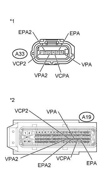
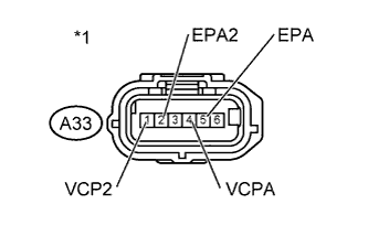
Text in Illustration *1 Front view of wire harness connector
(to Accelerator Pedal Position Sensor)
*2 Front view of wire harness connector
(to ECM)
Disconnect the accelerator pedal position sensor connector.
-
Disconnect the ECM connector.
-
Measure the resistance according to the value(s) in the table below.
Standard Resistance (Check for Open) Tester Connection Condition Specified Condition A33-1 (VCP2) - A19-53 (VCP2) Always Below 1 Ω A33-2 (EPA2) - A19-54 (EPA2) Always Below 1 Ω A33-3 (VPA2) - A19-52 (VPA2) Always Below 1 Ω A33-4 (VCPA) - A19-56 (VCPA) Always Below 1 Ω A33-5 (EPA) - A19-57 (EPA) Always Below 1 Ω A33-6 (VPA) - A19-55 (VPA) Always Below 1 Ω Standard Resistance (Check for Short) Tester Connection Condition Specified Condition A33-1 (VCP2) or A19-53 (VCP2) - Body ground Always 10 kΩ or higher A33-2 (EPA2) or A19-54 (EPA2) - Body ground Always 10 kΩ or higher A33-3 (VPA2) or A19-52 (VPA2) - Body ground Always 10 kΩ or higher A33-4 (VCPA) or A19-56 (VCPA) - Body ground Always 10 kΩ or higher A33-5 (EPA) or A19-57 (EPA) - Body ground Always 10 kΩ or higher A33-6 (VPA) or A19-55 (VPA) - Body ground Always 10 kΩ or higher -
Reconnect the accelerator pedal position sensor connector.
-
Reconnect the ECM connector.
NG
REPAIR OR REPLACE HARNESS OR CONNECTOR Click here
OK 
-
-
INSPECT ECM TERMINAL VOLTAGE (VCPA AND VCP2 TERMINALS)
-
Text in Illustration *1 Front view of wire harness connector
(to Accelerator Pedal Position Sensor)
Disconnect the accelerator pedal position sensor connector.
-
Measure the voltage according to the value(s) in the table below.
Standard Voltage Tester Connection Switch Condition Specified Condition A33-4 (VCPA) - A33-5 (EPA) Ignition switch ON 4.5 to 5.5 V A33-1 (VCP2) - A33-2 (EPA2) Ignition switch ON 4.5 to 5.5 V -
Reconnect the accelerator pedal position sensor connector.
NG
REPLACE ECM Click here
OK
-
-
REPLACE ACCELERATOR PEDAL SENSOR ASSEMBLY
-
Replace the accelerator pedal sensor assembly Click here.
NEXT
-
-
CHECK WHETHER DTC OUTPUT RECURS
-
Connect the intelligent tester to the DLC3.
-
Clear the DTCs Click here.
-
Turn the ignition switch off and wait for 30 seconds or more.
-
Turn the ignition switch to ON.
-
Fully close the accelerator pedal for 3 seconds, and then hold it partway open for 3 seconds, then fully open it for 3 seconds.
-
Enter the following menus: Powertrain / Engine and ECT / DTC.
-
Read the DTCs.
Result Result Proceed to DTC P1120 A No DTC output B
B 
END
A
-
-
REPLACE ECM
-
Replace the ECM Click here.
NEXT
CONFIRM WHETHER MALFUNCTION HAS BEEN SUCCESSFULLY REPAIRED Click here
-
-
REPAIR OR REPLACE HARNESS OR CONNECTOR
NEXT
-
CONFIRM WHETHER MALFUNCTION HAS BEEN SUCCESSFULLY REPAIRED
-
Connect the intelligent tester to the DLC3.
-
Clear the DTCs Click here.
-
Turn the ignition switch off and wait for 30 seconds or more.
-
Turn the ignition switch to ON.
-
Fully close the accelerator pedal for 3 seconds, and then hold it partway open for 3 seconds, then fully open it for 3 seconds.
-
Enter the following menus: Powertrain / Engine and ECT / DTC.
-
Confirm that the DTC is not output again.
NEXT 
END
-