СИСТЕМА ECD, Diagnostic DTC:P0685
| DTC Code | DTC Name |
|---|---|
| P0685 | ECM / PCM Power Relay Control Circuit / Open |
DESCRIPTION
The battery supplies power to terminal +B and/or +B1 of the ECM even when the ignition switch is turned to off (up to 15 seconds).
| DTC Detection Drive Pattern | DTC Detection Condition | Trouble Area |
|---|---|---|
| After ignition switch is turned to off | Either of following conditions is met: (1 trip detection logic)
|
|
Tech Tips
If DTC P0685 is stored, the ECM does not store other DTCs.
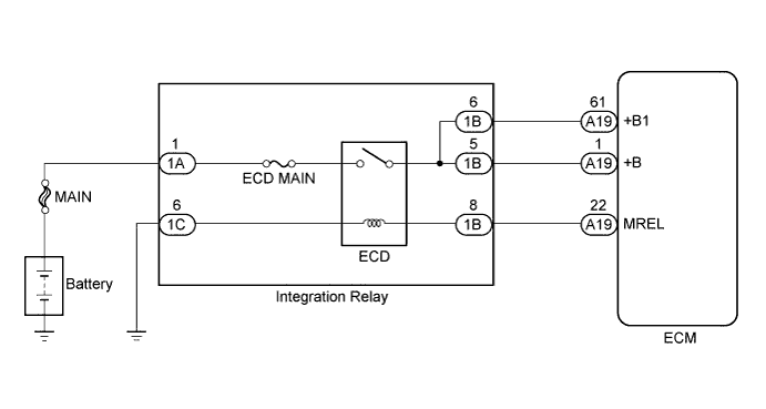
WIRING DIAGRAM
INSPECTION PROCEDURE
Note
-
When replacing the ECM, the ECM needs Registration and Initialization Click here.
-
Inspect the fuses for circuits related to this system before performing the following inspection procedure.
Tech Tips
When the ECM must be replaced, before replacing the ECM, perform the "Learning Values Save" function using the intelligent tester. Then after installing the new ECM, perform all of the initializations/registrations for the "Learning Values Write" function by following the instructions shown on the tester display.
PROCEDURE
-
INSPECT INTEGRATION NO.1 RELAY
-
Remove the integration relay from the engine room relay block.
-
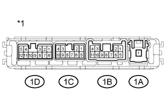
Text in Illustration *1 Lower side of component without harness connected
(Integration Relay)
Disconnect the integration relay connectors.
-
Measure the resistance according to the value(s) in the table below.
Standard Resistance Tester Connection Condition Specified Condition 1A-1 - 1B-5
1A-1 - 1B-6
When battery voltage absent 10 kΩ or higher When battery voltage applied to terminals 1B-8 - 1C-6 Below 1 Ω -
Reconnect the integration relay connectors.
-
Reinstall the integration relay.
NG 
REPLACE INTEGRATION NO.1 RELAY Click here
OK 
-
-
CHECK HARNESS AND CONNECTOR (INTEGRATION RELAY - ECM)
-
Disconnect the integration relay connector.
-
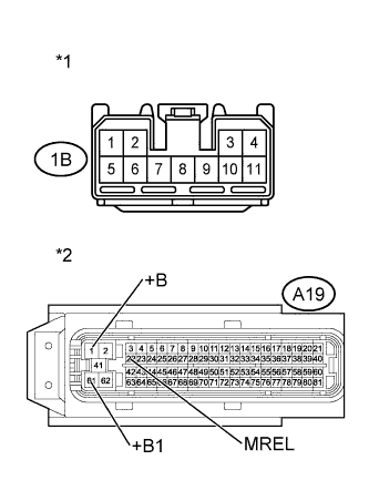
Text in Illustration *1 Front view of wire harness connector
(to Integration Relay)
*2 Front view of wire harness connector
(to ECM)
Disconnect the ECM connector.
-
Measure the resistance according to the value(s) in the table below.
Standard Resistance (Check for Open) Tester Connection Condition Specified Condition 1B-8 - A19-22 (MREL) Always Below 1 Ω 1B-5 - A19-1 (+B) Always Below 1 Ω 1B-6 - A19-61 (+B1) Always Below 1 Ω Standard Resistance (Check for Short) Tester Connection Condition Specified Condition 1B-8 or A19-22 (MREL) - Body ground Always 10 kΩ or higher 1B-5 or A19-1 (+B) - Body ground Always 10 kΩ or higher 1B-6 or A19-61 (+B1) - Body ground Always 10 kΩ or higher -
Reconnect the integration relay connector.
-
Reconnect the ECM connector.
NG
REPAIR OR REPLACE HARNESS OR CONNECTOR Click here
OK
-
-
REPLACE ECM
-
Replace the ECM Click here.
NEXT
CONFIRM WHETHER MALFUNCTION HAS BEEN SUCCESSFULLY REPAIRED Click here
-
-
REPAIR OR REPLACE HARNESS OR CONNECTOR
NEXT
CONFIRM WHETHER MALFUNCTION HAS BEEN SUCCESSFULLY REPAIRED Click here
-
REPLACE INTEGRATION NO.1 RELAY
-
Replace the integration relay Click here.
NEXT
-
-
CONFIRM WHETHER MALFUNCTION HAS BEEN SUCCESSFULLY REPAIRED
-
Connect the intelligent tester to the DLC3.
-
Turn the ignition switch to ON and turn the tester on.
-
Clear the DTCs Click here.
-
Turn the ignition switch off and wait for 30 seconds or more.
-
Turn the ignition switch to ON.
-
Enter the following menus: Powertrain / Engine and ECT / DTC.
-
Confirm that the DTC is not output again.
NEXT 
END
-