СИСТЕМА ECD, Diagnostic DTC:P0651
| DTC Code | DTC Name |
|---|---|
| P0651 | Sensor Reference Voltage "B" Circuit / Open |
DESCRIPTION
Refer to DTC P0192 Click here, DTC P0405 Click here and DTC P2564 Click here.
| DTC Detection Drive Pattern | DTC Detection Condition | Trouble Area |
|---|---|---|
| Ignition switch is ON | Power voltage (5 V as standard) supplied from ECM to nozzle vane position sensor, fuel pressure sensor and EGR valve position sensor are lower or higher than threshold. (1 trip detection logic) |
|
WIRING DIAGRAM
DTC P0192 Click here, DTC P0405 Click here and DTC P2564 Click here.
INSPECTION PROCEDURE
Note
When replacing the ECM, the ECM needs Registration and Initialization Click here.
Tech Tips
-
When the ECM must be replaced, before replacing the ECM, perform the "Learning Values Save" function using the intelligent tester. Then after installing the new ECM, perform all of the initializations/registrations for the "Learning Values Write" function by following the instructions shown on the tester display.
-
Read freeze frame data using the intelligent tester. Freeze frame data records the engine condition when malfunctions are detected. When troubleshooting, freeze frame data can help determine if the vehicle was moving or stationary, if the engine was warmed up or not, and other data from the time the malfunction occurred.
PROCEDURE
-
CHECK HARNESS AND CONNECTOR (NOZZLE VANE POSITION SENSOR - ECM))
-
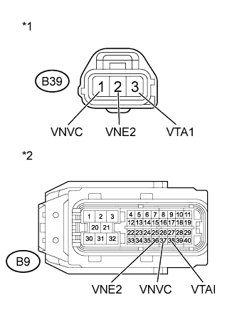
Text in Illustration *1 Front view of wire harness connector
(to Nozzle Vane Position Sensor)
*2 Front view of wire harness connector
(to ECM)
Disconnect the nozzle vane position sensor connector.
-
Disconnect the ECM connector.
-
Measure the resistance according to the value(s) in the table below.
Standard Resistance (Check for Short) Tester Connection Condition Specified Condition B39-3 (VTA1) or B9-38 (VTAI) - Body ground Always 10 kΩ or higher B39-1 (VNVC) or B9-37 (VNVC) - Body ground Always 10 kΩ or higher B39-2 (VNE2) or B9-36 (VNE2) - Body ground Always 10 kΩ or higher -
Reconnect the nozzle vane position sensor connector.
-
Reconnect the ECM connector.
NG 
REPAIR OR REPLACE HARNESS OR CONNECTOR Click here
OK 
-
-
INSPECT ECM (VC VOLTAGE)
-
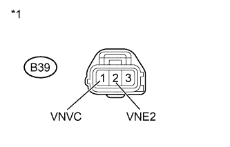
Text in Illustration *1 Front view of wire harness connector
(to Nozzle Vane Position Sensor)
Disconnect the nozzle vane position sensor connector.
-
Turn the ignition switch to ON.
-
Measure the voltage according to the value(s) in the table below.
Standard Voltage Tester Connection Switch Condition Specified Condition B39-1 (VNVC) - B39-2 (VNE2) Ignition switch ON 4.5 to 5.5 V -
Reconnect the nozzle vane position sensor connector.
NG
REPLACE ECM Click here
OK
-
-
CHECK HARNESS AND CONNECTOR (FUEL PRESSURE SENSOR - ECM)
-
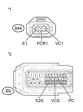
Text in Illustration *1 Front view of wire harness connector
(to Fuel Pressure Sensor)
*2 Front view of wire harness connector
(to ECM)
Disconnect the fuel pressure sensor connector.
-
Disconnect the ECM connector.
-
Measure the resistance according to the value(s) in the table below.
Standard Resistance (Check for Short) Tester Connection Condition Specified Condition B44-2 (PCR1) or B9-16 (PC) - Body ground Always 10 kΩ or higher B44-3 (VC1) or B9-15 (VCS) - Body ground Always 10 kΩ or higher B44-1 (E1) or B9-14 (E2S) - Body ground Always 10 kΩ or higher -
Reconnect the fuel pressure sensor connector.
-
Reconnect the ECM connector.
NG
REPAIR OR REPLACE HARNESS OR CONNECTOR Click here
OK
-
-
INSPECT ECM (VC VOLTAGE)
-
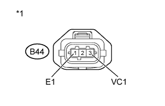
Text in Illustration *1 Front view of wire harness connector
(to Fuel Pressure Sensor)
Disconnect the fuel pressure sensor connector.
-
Turn the ignition switch to ON.
-
Measure the voltage according to the value(s) in the table below.
Standard Voltage Tester Connection Switch Condition Specified Condition B44-3 (VC1) - B44-1 (E1) Ignition switch ON 4.5 to 5.5 V -
Reconnect the fuel pressure sensor connector.
NG
REPLACE ECM Click here
OK
-
-
CHECK HARNESS AND CONNECTOR (ELECTRIC EGR VALVE ASSEMBLY - ECM)
-
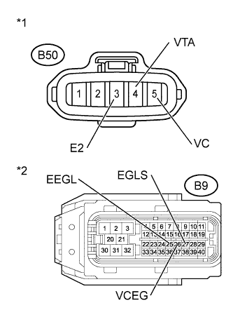
Text in Illustration *1 Front view of wire harness connector
(to Electric EGR Valve Assembly)
*2 Front view of wire harness connector
(to ECM)
Disconnect the electric EGR valve assembly connector.
-
Disconnect the ECM connector.
-
Measure the resistance according to the value(s) in the table below.
Standard Resistance (Check for Short) Tester Connection Condition Specified Condition B50-5 (VC) or B9-26 (VCEG) - Body ground Always 10 kΩ or higher B50-4 (VTA) or B9-27 (EGLS) - Body ground Always 10 kΩ or higher B50-3 (E2) or B9-25 (EEGL) - Body ground Always 10 kΩ or higher -
Reconnect the electric EGR valve assembly connector.
-
Reconnect the ECM connector.
NG
REPAIR OR REPLACE HARNESS OR CONNECTOR Click here
OK
-
-
INSPECT ECM (VC VOLTAGE)
-
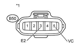
Text in Illustration *1 Front view of wire harness connector
(to Electric EGR Valve Assembly)
Disconnect the electric EGR valve assembly connector.
-
Turn the ignition switch to ON.
-
Measure the voltage according to the value(s) in the table below.
Standard Voltage Tester Connection Switch Condition Specified Condition B50-5 (VC) - B50-3 (E2) Ignition switch ON 4.5 to 5.5 V -
Reconnect the electric EGR valve assembly connector.
NG
REPLACE ECM Click here
OK
-
-
REPLACE TURBOCHARGER SUB-ASSEMBLY (NOZZLE VANE POSITION SENSOR)
-
Replace the turbocharger sub-assembly Click here.
NEXT
-
-
CHECK WHETHER DTC OUTPUT RECURS (DTC P0651)
-
Connect the intelligent tester to the DLC3.
-
Turn the ignition switch to ON and turn the tester on.
-
Clear the DTCs Click here.
-
Turn the ignition switch off.
-
Turn the ignition switch to ON.
-
Turn the ignition switch off and wait for 30 seconds or more.
-
Turn the ignition switch to ON and wait for 10 seconds or more.
-
Enter the following menus: Powertrain / Engine and ECT / DTC.
-
Read the DTC.
Result Result Proceed to No DTC output A P0651 B
B
REPLACE COMMON RAIL ASSEMBLY (FUEL PRESSURE SENSOR) Click here
A 
END
-
-
REPLACE COMMON RAIL ASSEMBLY (FUEL PRESSURE SENSOR)
-
Replace the common rail assembly Click here.
NEXT
-
-
BLEED AIR FROM FUEL SYSTEM
-
Bleed air from fuel system Click here.
NEXT
-
-
CHECK WHETHER DTC OUTPUT RECURS (DTC P0651)
-
Connect the intelligent tester to the DLC3.
-
Turn the ignition switch to ON and turn the tester on.
-
Clear the DTCs Click here.
-
Turn the ignition switch off and wait for 30 seconds or more.
-
Turn the ignition switch to ON.
-
Enter the following menus: Powertrain / Engine and ECT / DTC.
-
Read the DTC.
Result Result Proceed to No DTC output A P0651 B
B
REPLACE ELECTRIC EGR CONTROL VALVE ASSEMBLY (EGR VALVE POSITION SENSOR) Click here
A
END
-
-
REPLACE ELECTRIC EGR CONTROL VALVE ASSEMBLY (EGR VALVE POSITION SENSOR)
-
Replace the electric EGR valve assembly Click here.
NEXT
CONFIRM WHETHER MALFUNCTION HAS BEEN SUCCESSFULLY REPAIRED Click here
-
-
REPAIR OR REPLACE HARNESS OR CONNECTOR
NEXT
CONFIRM WHETHER MALFUNCTION HAS BEEN SUCCESSFULLY REPAIRED Click here
-
REPLACE ECM
-
Replace the ECM Click here.
NEXT
-
-
CONFIRM WHETHER MALFUNCTION HAS BEEN SUCCESSFULLY REPAIRED
-
Connect the intelligent tester to the DLC3.
-
Turn the ignition switch to ON and turn the tester on.
-
Clear the DTCs Click here.
-
Turn the ignition switch off.
-
Turn the ignition switch to ON.
-
Turn the ignition switch off and wait for 30 seconds or more.
-
Turn the ignition switch to ON and wait for 10 seconds or more.
-
Enter the following menus: Powertrain / Engine and ECT / DTC.
-
Confirm that the DTC is not output again.
NEXT
END
-