СИСТЕМА ECD Pre-heating Control Circuit
DESCRIPTION
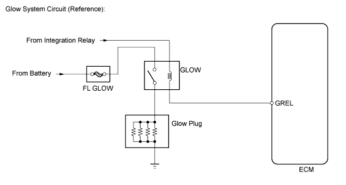
The glow plug is mounted inside the engine combustion chamber. To ensure efficient engine starting with a cold engine, the ECM calculates a time interval during which current needs to flow through the glow plug, depending on the starting engine coolant temperature when the ignition switch is turned to ON. The ECM then turns on the glow plug relay and permits the current to flow through the glow plug based on the ECM calculated time. The glow plug is then heated, and enhances fuel combustion with a cold engine.
Tech Tips
-
These troubleshooting procedures are for: 1) difficult engine starting in cold weather, and 2) difficulty driving/vehicle malfunctions in cold weather immediately after engine is started.
-
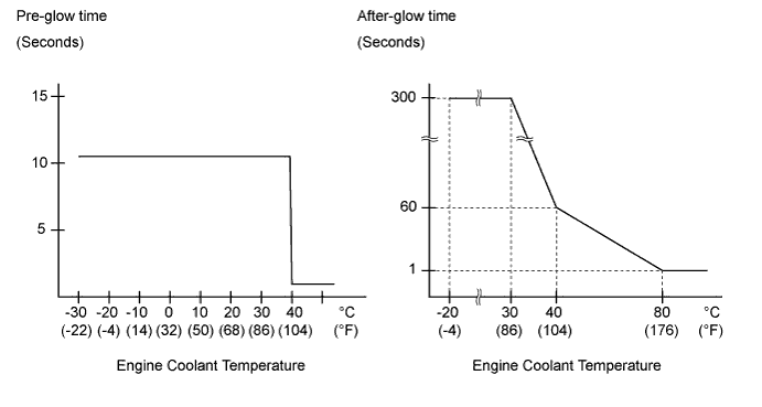
After the engine is started, the ECM performs an "after-glow" for a certain period of time. In proportion to the actual engine coolant temperature, the time period varies. The after-glow reduces diesel engine knocking, white smoke emissions and engine noises when the engine is cold.
-
Pre-glow time depends on battery voltage and engine coolant temperature.
-
After-glow time depends on atmospheric pressure and engine coolant temperature.
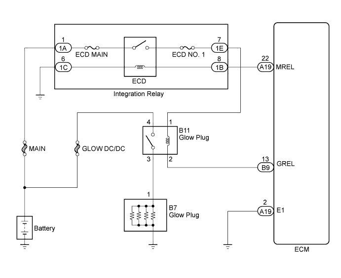
WIRING DIAGRAM
INSPECTION PROCEDURE
Note
Inspect the fuse for circuits related to this system before performing the following inspection procedure.
PROCEDURE
-
INSPECT GLOW PLUG RELAY ASSEMBLY
-
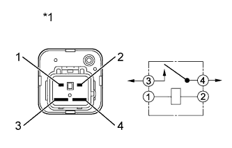
Text in Illustration *1 Component without harness connected
(Glow Plug Relay)
Disconnect the glow plug relay connector.
-
Measure the resistance according to the value(s) in the table below.
Standard Resistance Tester Connection Condition Specified Condition 3 - 4 Battery voltage absent 10 kΩ or higher 3 - 4 Battery voltage applied to terminal 1 - 2 Below 1 Ω -
Reconnect the glow plug relay connector.
NG 
REPLACE GLOW PLUG RELAY ASSEMBLY
OK 
-
-
INSPECT GLOW PLUG ASSEMBLY (RESISTANCE)
-
Inspect the glow plug assembly Click here.
NG
REPLACE GLOW PLUG ASSEMBLY Click here
OK
-
-
CHECK GLOW PLUG ASSEMBLY (INSTALLATION)
-
Check the glow plug installation Click here.
NG
TIGHTEN GLOW PLUG Click here
OK
-
-
CHECK HARNESS AND CONNECTOR (GLOW PLUG RELAY - ECM)
-
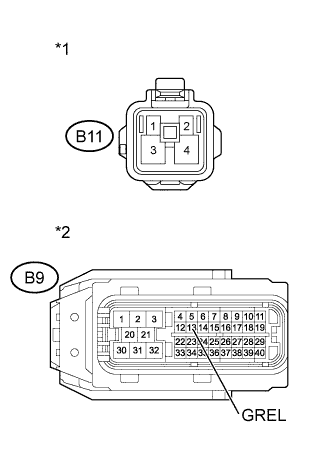
Text in Illustration *1 Front view of wire harness connector
(to Glow Plug Relay)
*2 Front view of wire harness connector
(to ECM)
Disconnect the glow plug relay connector.
-
Disconnect the ECM connector.
-
Measure the resistance according to the value(s) in the table below.
Standard Resistance (Check for Open) Tester Connection Condition Specified Condition B11-2 - B9-13 (GREL) Always Below 1 Ω Standard Resistance (Check for Short) Tester Connection Condition Specified Condition B11-2 or B9-13 (GREL) - Body ground Always 10 kΩ or higher -
Reconnect the glow plug relay connector.
-
Reconnect the ECM connector.
NG
REPAIR OR REPLACE HARNESS OR CONNECTOR
OK
-
-
CHECK HARNESS AND CONNECTOR (GLOW PLUG RELAY - INTEGRATION RELAY)
-
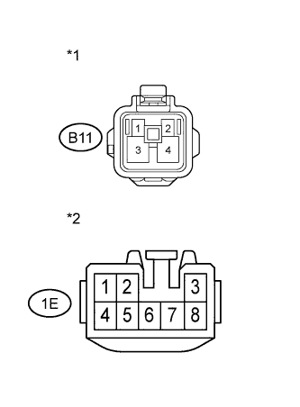
Text in Illustration *1 Front view of wire harness connector
(to Glow Plug Relay)
*2 Front view of wire harness connector
(to Integration Relay)
Remove the integration relay from the engine room relay block.
-
Disconnect the integration relay connector.
-
Disconnect the glow plug relay connector.
-
Measure the resistance according to the value(s) in the table below.
Standard Resistance (Check for Open) Tester Connection Condition Specified Condition B11-1 - 1E-7 Always Below 1 Ω Standard Resistance (Check for Short) Tester Connection Condition Specified Condition B11-1 or 1E-7 - Body ground Always 10 kΩ or higher -
Reconnect the glow plug relay connector.
-
Reconnect the integration relay connector.
-
Reinstall the integration relay.
NG
REPAIR OR REPLACE HARNESS OR CONNECTOR
OK
-
-
CHECK ECM POWER SOURCE CIRCUIT
-
Check the ECM power source circuit Click here.
NG
REPAIR OR REPLACE HARNESS OR CONNECTOR
OK
-
-
CHECK HARNESS AND CONNECTOR (GLOW PLUG - GLOW PLUG RELAY - BATTERY)
-
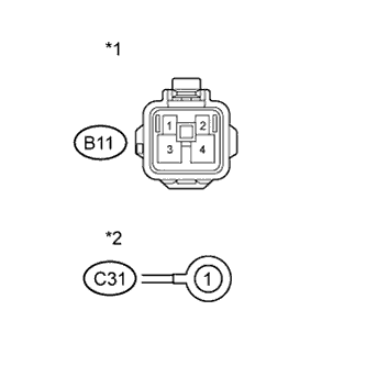
Text in Illustration *1 Front view of wire harness connector
(to Glow Plug Relay)
*2 Front view of wire harness connector
(to Glow Plug)
Disconnect the glow plug relay connector.
-
Disconnect the glow plug wire.
-
Measure the resistance according to the value(s) in the table below.
Standard Resistance (Check for Open) Tester Connection Condition Specified Condition B11-3 - B7-1 Always Below 1 Ω B11-4 - Battery positive terminal Always Below 1 Ω -
Reconnect the glow plug wire.
-
Reconnect the glow plug relay connector.
NG
REPAIR OR REPLACE HARNESS OR CONNECTOR
OK 
REPLACE ECM Click here
-