СИСТЕМА ECD, Diagnostic DTC:P0380
| DTC Code | DTC Name |
|---|---|
| P0380 | Glow Plug / Heater Circuit "A" Malfunction |
DESCRIPTION
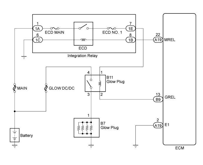
The glow plug is mounted inside the engine combustion chamber. To ensure efficient engine starting with a cold engine, the ECM calculates the time interval the current needs to flow through the glow plug, depending on the starting engine coolant temperature when the ignition switch is turned to ON. The ECM then turns on the glow plug relay and permits the current to flow through the glow plug based on the calculated time of the ECM. The glow plug is then heated, and enhances fuel combustion with a cold engine.
| DTC Detection Drive Pattern | DTC Detection Condition | Trouble Area |
|---|---|---|
| Ignition switch ON for 1 second | Open or short in glow plug relay circuit. (2 trip detection logic) |
|
| DTC No. | Data List |
|---|---|
| P0380 |
|
Tech Tips
-
If DTC P0380 is stored, the following symptoms may appear:
-
Difficult starting
WIRING DIAGRAM
INSPECTION PROCEDURE
Note
-
When replacing the ECM, the ECM needs Registration and Initialization Click here.
-
Inspect the fuse for circuits related to this system before performing the following inspection procedure
Tech Tips
-
When the ECM must be replaced, before replacing the ECM, perform the "Learning Values Save" function using the intelligent tester. Then after installing the new ECM, perform all of the initializations/registrations for the "Learning Values Write" function by following the instructions shown on the tester display.
-
Read freeze frame data using the intelligent tester. Freeze frame data records the engine condition when malfunctions are detected. When troubleshooting, freeze frame data can help determine if the vehicle was moving or stationary, if the engine was warmed up or not, and other data from the time the malfunction occurred.
PROCEDURE
-
READ VALUE USING INTELLIGENT TESTER (PRE GLOW AND AFTER GLOW)
-
Connect the intelligent tester to the DLC3.
-
Turn the ignition switch to ON and turn the tester on.
-
Enter the following menus: Powertrain / Engine and ECT / Data List / Pre Glow and After Glow.
-
Read the values when before and after start the engine.
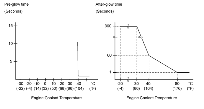
OK "Pre Glow" is ON before starting the engine and "After Glow" is ON after starting the engine. Tech Tips
"Pre Glow" and "After Glow" times vary depending on the engine coolant temperature sensor as shown in the illustration.
Tech Tips
-
Pre-glow time depends on battery voltage and engine coolant temperature.
-
After-glow time depends on atmospheric pressure and engine coolant temperature.
-
NG 
INSPECT GLOW PLUG RELAY ASSEMBLY Click here
OK 
CHECK FOR INTERMITTENT PROBLEMS Click here
-
-
INSPECT GLOW PLUG RELAY ASSEMBLY
-
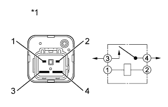
Text in Illustration *1 Component without harness connected
(Glow Plug Relay)
Disconnect the glow plug relay connector.
-
Measure the resistance according to the value(s) in the table below.
Standard Resistance Tester Connection Condition Specified Condition 3 - 4 When battery voltage absent 10 kΩ or higher When battery voltage applied to terminal 1 - 2 Below 1 Ω -
Reconnect the glow plug relay connector.
NG
REPLACE GLOW PLUG RELAY ASSEMBLY Click here
OK 
-
-
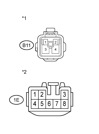
CHECK HARNESS AND CONNECTOR (GLOW PLUG RELAY - ECM)
-
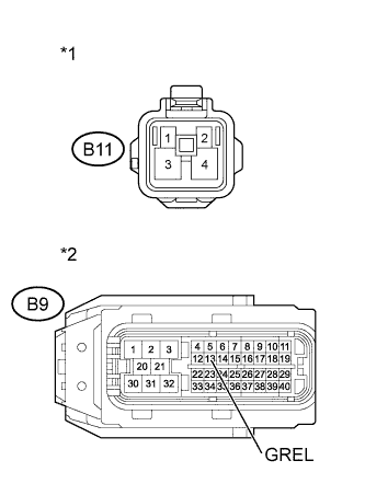
Text in Illustration *1 Front view of wire harness connector
(to Glow Plug Relay)
*2 Front view of wire harness connector
(to ECM)
Disconnect the glow plug relay connector.
-
Disconnect the ECM connector.
-
Measure the resistance according to the value(s) in the table below.
Standard Resistance (Check for Open) Tester Connection Condition Specified Condition B11-2 - B9-13 (GREL) Always Below 1 Ω Standard Resistance (Check for Short) Tester Connection Condition Specified Condition B11-2 or B9-13 (GREL) - Body ground Always 10 kΩ or higher -
Reconnect the glow plug relay connector.
-
Reconnect the ECM connector.
NG
REPAIR OR REPLACE HARNESS OR CONNECTOR Click here
OK
-
-
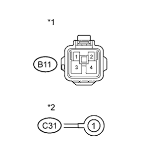
CHECK HARNESS AND CONNECTOR (GLOW PLUG RELAY - INTEGRATION RELAY)
-
Text in Illustration *1 Front view of wire harness connector
(to Glow Plug Relay)
*2 Front view of wire harness connector
(to Integration Relay)
Remove the integration relay from the engine room relay block.
-
Disconnect the integration relay connector.
-
Disconnect the glow plug relay connector.
-
Measure the resistance according to the value(s) in the table below.
Standard Resistance (Check for Open) Tester Connection Condition Specified Condition B11-1 - 1E-7 Always Below 1 Ω Standard Resistance (Check for Short) Tester Connection Condition Specified Condition B11-1 or 1E-7 - Body ground Always 10 kΩ or higher -
Reconnect the glow plug relay connector.
-
Reconnect the integration relay connector.
-
Reinstall the integration relay.
NG
REPAIR OR REPLACE HARNESS OR CONNECTOR Click here
OK
-
-
CHECK HARNESS AND CONNECTOR (GLOW PLUG - GLOW PLUG RELAY - BATTERY)
-
Text in Illustration *1 Front view of wire harness connector
(to Glow Plug Relay)
*2 Front view of wire harness connector
(to Glow Plug)
Disconnect the glow plug relay connector.
-
Disconnect the glow plug wire.
-
Measure the resistance according to the value(s) in the table below.
Standard Resistance (Check for Open) Tester Connection Condition Specified Condition B11-3 - B7-1 Always Below 1 Ω B11-4 - Battery positive terminal Always Below 1 Ω -
Reconnect the glow plug wire.
-
Reconnect the glow plug relay connector.
NG
REPAIR OR REPLACE HARNESS OR CONNECTOR Click here
OK
-
-
REPLACE ECM
-
Replace the ECM Click here.
NEXT
CONFIRM WHETHER MALFUNCTION HAS BEEN SUCCESSFULLY REPAIRED Click here
-
-
REPLACE GLOW PLUG RELAY ASSEMBLY
-
Replace the glow plug relay assembly.
NEXT
CONFIRM WHETHER MALFUNCTION HAS BEEN SUCCESSFULLY REPAIRED Click here
-
-
REPAIR OR REPLACE HARNESS OR CONNECTOR
NEXT
-
CONFIRM WHETHER MALFUNCTION HAS BEEN SUCCESSFULLY REPAIRED
-
Connect the intelligent tester to the DLC3.
-
Clear the DTCs Click here.
-
Turn the ignition switch off.
-
Turn the ignition switch to ON.
-
Confirm that the DTC is not output again.
NEXT
END
-