СИСТЕМА ECD, Diagnostic DTC:P0335, P0339
| DTC Code | DTC Name |
|---|---|
| P0335 | Crankshaft Position Sensor "A" Circuit |
| P0339 | Crankshaft Position Sensor "A" Circuit Intermittent |
DESCRIPTION
The crankshaft position sensor system consists of a crankshaft position sensor plate and a pickup coil.
The sensor plate has 58 teeth and is installed on the crankshaft. The pickup coil is made of an iron core and a magnet. The sensor plate rotates and as each tooth passes through the pickup coil, a pulse signal is created.
The pickup coil generates 58 signals per engine revolution. Based on these signals, the ECM calculates the crankshaft position and engine speed. Using these calculations, the common rail system is controlled.
| DTC Detection Drive Pattern | DTC Detection Condition | Trouble Area |
|---|---|---|
| The engine cranks 10 revolutions or more | No crankshaft position sensor signal to ECM while cranking (1 trip detection logic) |
|
| DTC Detection Drive Pattern | DTC Detection Condition | Trouble Area |
|---|---|---|
| The engine cranks 4 revolutions or more | Wrong pattern of signal from sensor is detected (1 trip detection logic) |
|
| DTC No. | Data List |
|---|---|
| P0335 |
|
| P0339 |
Tech Tips
-
If DTC P0335 and/or P0339 is stored, the following symptoms may appear:
-
Difficult to start
-
Engine stalls due to fail-safe operation (fuel cut)
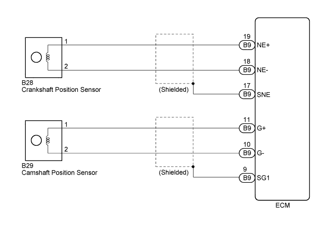
WIRING DIAGRAM
INSPECTION PROCEDURE
Note
When replacing the ECM and/or engine assembly, the ECM needs Registration and Initialization Click here.
Tech Tips
-
When the ECM must be replaced, before replacing the ECM, perform the "Learning Values Save" function using the intelligent tester. Then after installing the new ECM, perform all of the initializations/registrations for the "Learning Values Write" function by following the instructions shown on the tester display.
-
Check the value on the intelligent tester.
-
Connect the intelligent tester to the DLC3.
-
Start the engine and turn the tester on.
-
Enter the following menus: Powertrain / Engine and ECT / Data List / Engine Speed.
-
The engine speed can be confirmed in the Data List using the intelligent tester. If there are no NE signals from the crankshaft position sensor despite the engine revolving, the engine speed will be indicated as zero. If the voltage output of the crankshaft position sensor is insufficient, the engine speed will be indicated as lower than the actual engine rpm.
-
Read freeze frame data using the intelligent tester. Freeze frame data records the engine condition when malfunctions are detected. When troubleshooting, freeze frame data can help determine if the vehicle was moving or stationary, if the engine was warmed up or not, and other data from the time the malfunction occurred.
PROCEDURE
-
INSPECT CRANKSHAFT POSITION SENSOR
-
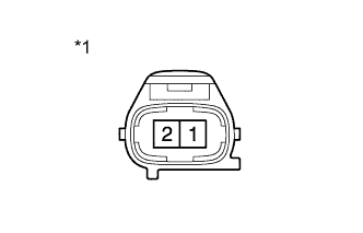
Text in Illustration *1 Component without harness connected
(Crankshaft Position Sensor)
Disconnect the crankshaft position sensor connector.
-
Measure the resistance according to the value(s) in the table below.
Standard Resistance Tester Connection Condition Specified Condition 1 - 2 20°C (68°F) 1850 to 2450 Ω -
Reconnect the crankshaft position sensor connector.
NG 
REPLACE CRANKSHAFT POSITION SENSOR Click here
OK 
-
-
CHECK HARNESS AND CONNECTOR (CRANKSHAFT POSITION SENSOR - ECM)
-
Disconnect the crankshaft position sensor connector.
-
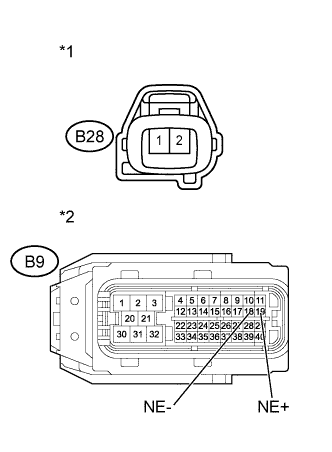
Text in Illustration *1 Front view of wire harness connector
(to Crankshaft Position Sensor)
*2 Front view of wire harness connector
(to ECM)
Disconnect the ECM connector.
-
Measure the resistance according to the value(s) in the table below.
Standard Resistance (Check for Open) Tester Connection Condition Specified Condition B28-1 - B9-19 (NE+) Always Below 1 Ω B28-2 - B9-18 (NE-) Always Below 1 Ω Standard Resistance (Check for Short) Tester Connection Condition Specified Condition B28-1 or B9-19 (NE+) - Body ground Always 10 kΩ or higher B28-2 or B9-18 (NE-) - Body ground Always 10 kΩ or higher Tech Tips
A DTC may also be stored when the ground of a shielded wire is faulty.
-
Reconnect the crankshaft position sensor.
-
Reconnect the ECM connector.
NG
REPAIR OR REPLACE HARNESS OR CONNECTOR Click here
OK
-
-
CHECK SENSOR INSTALLATION (CRANKSHAFT POSITION SENSOR)
-
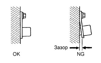
Check the crankshaft position sensor installation.
OK Sensor is installed correctly.
NG
SECURELY REINSTALL SENSOR Click here
OK
-
-
CHECK CRANKSHAFT POSITION SENSOR PLATE NO. 1 (TEETH OF SENSOR PLATE)
-
Check the teeth of the sensor plate.
OK Sensor plate does not have any cracks or deformation.
NG
REPLACE CRANKSHAFT POSITION SENSOR PLATE NO. 1 Click here
OK
-
-
REPLACE ECM
-
Replace the ECM Click here.
NEXT
CONFIRM WHETHER MALFUNCTION HAS BEEN SUCCESSFULLY REPAIRED Click here
-
-
REPLACE CRANKSHAFT POSITION SENSOR
-
Replace crankshaft position sensor Click here.
NEXT
CONFIRM WHETHER MALFUNCTION HAS BEEN SUCCESSFULLY REPAIRED Click here
-
-
REPAIR OR REPLACE HARNESS OR CONNECTOR
NEXT
CONFIRM WHETHER MALFUNCTION HAS BEEN SUCCESSFULLY REPAIRED Click here
-
SECURELY REINSTALL SENSOR
-
Securely reinstall sensor Click here.
NEXT
CONFIRM WHETHER MALFUNCTION HAS BEEN SUCCESSFULLY REPAIRED Click here
-
-
REPLACE CRANKSHAFT POSITION SENSOR PLATE NO. 1
-
Replace the crankshaft position sensor plate No. 1 Click here.
NEXT
-
-
CONFIRM WHETHER MALFUNCTION HAS BEEN SUCCESSFULLY REPAIRED
-
Connect the intelligent tester to the DLC3.
-
Clear DTCs Click here.
-
Start the engine.
-
Confirm that the DTC is not output again.
NEXT 
END
-