СИСТЕМА ECD, Diagnostic DTC:P0236, P0237, P0238
| DTC Code | DTC Name |
|---|---|
| P0236 | Turbocharger / Supercharger Boost Sensor "A" Circuit Range / Performance |
| P0237 | Turbocharger / Supercharger Boost Sensor "A" Circuit Low |
| P0238 | Turbocharger / Supercharger Boost Sensor "A" Circuit High |
DESCRIPTION
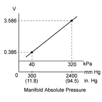
The turbo pressure sensor detects the intake manifold pressure. The ECM determines the basic injection duration and injection advance timing based on the voltage output from the turbo pressure sensor.
| DTC Detection Drive Pattern | DTC Detection Condition | Trouble Area |
|---|---|---|
| Engine idles for 10 seconds or more | The turbo pressure sensor output differs from atmospheric pressure sensor output by more than threshold for 2 seconds or more. (1 trip detection logic) |
|
| DTC Detection Drive Pattern | DTC Detection Condition | Trouble Area |
|---|---|---|
| Ignition switch is ON and 10 seconds elapsed | Short in turbo pressure sensor circuit for 5 seconds or more. (1 trip detection logic) |
|
| DTC Detection Drive Pattern | DTC Detection Condition | Trouble Area |
|---|---|---|
| Ignition switch is ON and 5 seconds elapsed | Open in turbo pressure sensor circuit for 1.5 seconds or more. (1 trip detection logic) |
|
| DTC No. | Data List |
|---|---|
| P0236 |
|
| P0237 | |
| P0238 |
Tech Tips
When DTC P0236, P0237 and/or P0238 are stored, check the intake manifold pressure by entering the following menus on the intelligent tester: Powertrain / Engine and ECT / Data List / MAP.
| Reference | ||||||
|---|---|---|---|---|---|---|
|
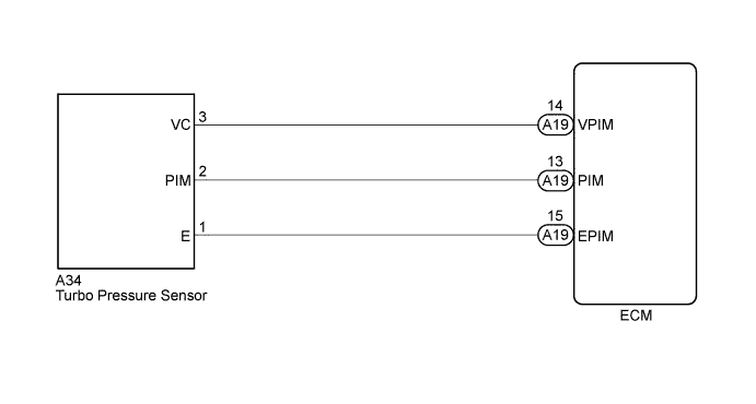
WIRING DIAGRAM
INSPECTION PROCEDURE
Note
When replacing the ECM, the ECM needs Registration and Initialization Click here.
Tech Tips
-
When the ECM must be replaced, before replacing the ECM, perform the "Learning Values Save" function using the intelligent tester. Then after installing the new ECM, perform all of the initializations/registrations for the "Learning Values Write" function by following the instructions shown on the tester display.
-
Read freeze frame data using the intelligent tester. Freeze frame data records the engine condition when malfunctions are detected. When troubleshooting, freeze frame data can help determine if the vehicle was moving or stationary, if the engine was warmed up or not, and other data from the time the malfunction occurred.
PROCEDURE
-
READ VALUE USING INTELLIGENT TESTER (MAP AND ATMOSPHERE PRESSURE)
-
Connect the intelligent tester to the DLC3.
-
Turn the ignition switch to ON and turn the tester on.
-
Enter the following menus: Powertrain / Engine and ECT / Data List / MAP and Atmosphere Pressure.
-
Compare the values when the ignition switch is ON.
Standard Difference between the MAP and the Atmosphere Pressure is less than 7 kPa. Tech Tips
Standard atmospheric pressure is 101 kPa. For every 100 m increase in altitude, pressure drops by 1 kPa. Varies by weather.
OK 
CONFIRM WHETHER MALFUNCTION HAS BEEN SUCCESSFULLY REPAIRED Click here
NG
CHECK HARNESS AND CONNECTOR (TURBO PRESSURE SENSOR - ECM) Click here
-
-
CHECK HARNESS AND CONNECTOR (TURBO PRESSURE SENSOR - ECM)
-
Disconnect the turbo pressure sensor connector.
-
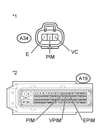
Text in Illustration *1 Front view of wire harness connector
(to Turbo Pressure Sensor)
*2 Front view of wire harness connector
(to ECM)
Disconnect the ECM connector.
-
Measure the resistance according to the value(s) in the table below.
Standard Resistance (Check for Open) Tester Connection Condition Specified Condition A34-2 - A19-13 (PIM) Always Below 1 Ω A34-3 - A19-14 (VPIM) Always Below 1 Ω A34-1 - A19-15 (EPIM) Always Below 1 Ω Standard Resistance (Check for Short) Tester Connection Condition Specified Condition A34-2 or A19-13 (PIM) - Body ground Always 10 kΩ or higher A34-3 or A19-14 (VPIM) - Body ground Always 10 kΩ or higher A34-1 or A19-15 (EPIM) - Body ground Always 10 kΩ or higher -
Reconnect the turbo pressure sensor connector.
-
Reconnect the ECM connector.
NG
REPAIR OR REPLACE HARNESS OR CONNECTOR Click here
OK 
-
-
CHECK ECM TERMINAL VOLTAGE (VC TERMINAL)
-
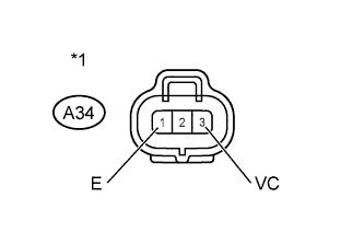
Text in Illustration *1 Front view of wire harness connector
(to Turbo Pressure Sensor)
Disconnect the turbo pressure sensor connector.
-
Turn the ignition switch to ON.
-
Measure the voltage according to the value(s) in the table below.
Standard Voltage Tester Connection Switch Condition Specified Condition A34-3 (VC) - A34-1 (E) Ignition switch ON 4.5 to 5.5 V -
Reconnect the turbo pressure sensor connector.
NG
REPLACE ECM Click here
OK
-
-
REPLACE TURBO PRESSURE SENSOR
-
Replace the turbo pressure sensor Click here.
NEXT
-
-
CHECK WHETHER DTC OUTPUT RECURS
-
Connect the intelligent tester to the DLC3.
-
Turn the ignition switch to ON and turn the tester on.
-
Clear the DTCs Click here.
-
Start the engine.
-
Allow the engine to idle for 10 seconds or more.
-
Enter the following menus: Powertrain / Engine and ECT / DTC.
-
Read the DTCs.
Result Result Proceed to DTC P0236, P0237 and/or P0238 A No DTC output B
B 
END
A
-
-
REPLACE ECM
-
Replace the ECM Click here.
NEXT
CONFIRM WHETHER MALFUNCTION HAS BEEN SUCCESSFULLY REPAIRED Click here
-
-
REPAIR OR REPLACE HARNESS OR CONNECTOR
NEXT
-
CONFIRM WHETHER MALFUNCTION HAS BEEN SUCCESSFULLY REPAIRED
-
Connect the intelligent tester to the DLC3.
-
Turn the ignition switch to ON and turn the tester on.
-
Clear the DTCs Click here.
-
Start the engine.
-
Allow the engine to idle for 10 seconds or more.
-
Enter the following menus: Powertrain / Engine and ECT / DTC.
-
Confirm that the DTC is not output again.
NEXT 
END
-