СИСТЕМА ECD, Diagnostic DTC:P0182, P0183
| DTC Code | DTC Name |
|---|---|
| P0182 | Fuel Temperature Sensor "A" Circuit Low Input |
| P0183 | Fuel Temperature Sensor "A" Circuit High Input |
DESCRIPTION
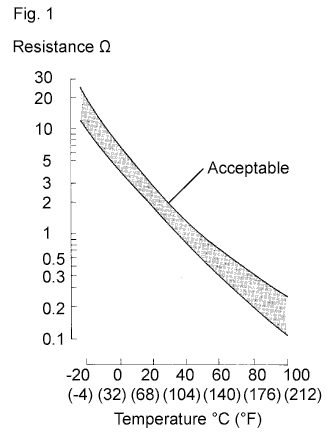
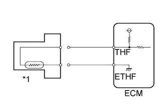
The fuel temperature sensor monitors the fuel temperature. The fuel temperature sensor has a thermistor that varies its resistance depending on the fuel temperature. When the fuel temperature is low, the resistance of the thermistor is high. When the temperature is high, the resistance is low.
The variations of resistance are communicated to the ECM as changes of voltage (See Fig. 1).
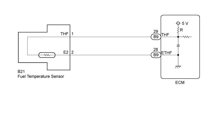
The fuel temperature sensor is connected to the ECM. The 5 V power source voltage in the ECM is applied to the fuel temperature sensor from terminal THF via resistor R.
Resistor R and the fuel temperature sensor are connected in series. When the resistance value of the fuel temperature sensor changes due to a change of fuel temperature, the voltage at terminal THF also changes. Based on this signal, the ECM corrects the pressure control compensation of the fuel supply pump and determines if there are errors.
Tech Tips
When the fuel temperature sensor output is outside the normal range, the ECM determines that this is a malfunction.
| DTC Detection Drive Pattern | DTC Detection Condition | Trouble Area |
|---|---|---|
| Engine idles for approximately 15 seconds | Open or short in fuel temperature sensor circuit for 2.0 seconds (1 trip detection logic) |
|
| DTC No. | Data List |
|---|---|
| P0182 |
|
| P0183 |
WIRING DIAGRAM
INSPECTION PROCEDURE
Note
When replacing the ECM, the ECM needs Registration and Initialization Click here.
Tech Tips
-
When the ECM must be replaced, before replacing the ECM, perform the "Learning Values Save" function using the intelligent tester. Then after installing the new ECM, perform all of the initializations/registrations for the "Learning Values Write" function by following the instructions shown on the tester display.
-
Read freeze frame data using the intelligent tester. Freeze frame data records the engine condition when malfunctions are detected. When troubleshooting, freeze frame data can help determine if the vehicle was moving or stationary, if the engine was warmed up or not, and other data from the time the malfunction occurred.
PROCEDURE
-
READ VALUE USING INTELLIGENT TESTER (FUEL TEMPERATURE)
-
Connect the intelligent tester to the DLC3.
-
Turn the ignition switch to ON and turn the tester on.
-
Enter the following menus: Powertrain / Engine and ECT / Data List / Fuel Temperature.
-
Read the value.
OK Same as actual fuel temperature. Result Result Proceed to -40°C (-40°F) A 149°C (300°F) or higher B Same as actual fuel temperature C Tech Tips
-
If there is an open circuit, the intelligent tester indicates -40°C (-40°F).
-
If there is a short circuit, the intelligent tester indicates 149°C (300°F) or higher.
-
B 
READ VALUE USING INTELLIGENT TESTER (CHECK FOR SHORT IN WIRE HARNESS) Click here
C
CONFIRM WHETHER MALFUNCTION HAS BEEN SUCCESSFULLY REPAIRED Click here
A 
-
-
READ VALUE USING INTELLIGENT TESTER (CHECK FOR OPEN IN WIRE HARNESS)
-
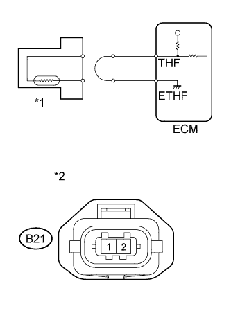
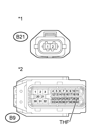
Text in Illustration *1 Fuel Temperature Sensor *2 Front view of wire harness connector
(to Fuel Temperature Sensor)
Disconnect the fuel temperature sensor connector.
-
Connect terminals THF and ETHF of the fuel temperature sensor wire harness side connector.
-
Connect the intelligent tester to the DLC3.
-
Turn the ignition switch to ON and turn the tester on.
-
Enter the following menus: Powertrain / Engine and ECT / Data List / Fuel Temperature.
-
Read the value.
Standard 149°C (300°F) or higher -
Reconnect the fuel temperature sensor connector.
OK
CONFIRM GOOD CONNECTION TO SENSOR. IF OK, REPLACE SUPPLY PUMP ASSEMBLY Click here
NG
CHECK HARNESS AND CONNECTOR (FUEL TEMPERATURE SENSOR - ECM) Click here
-
-
CHECK HARNESS AND CONNECTOR (FUEL TEMPERATURE SENSOR - ECM)
-
Disconnect the fuel temperature sensor connector.
-
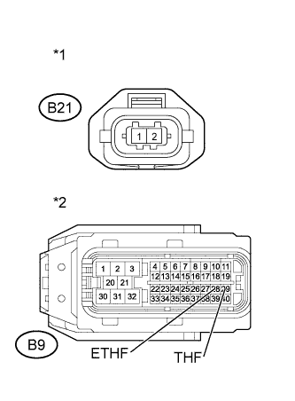
Text in Illustration *1 Front view of wire harness connector
(to Fuel Temperature Sensor)
*2 Front view of wire harness connector
(to ECM)
Disconnect the ECM connector.
-
Measure the resistance according to the value(s) in the table below.
Standard Resistance (Check for Open) Tester Connection Condition Specified Condition B21-1 (THF) - B9-29 (THF) Always Below 1 Ω B21-2 (E2) - B9-28 (ETHF) Always Below 1 Ω -
Reconnect the fuel temperature sensor connector.
-
Reconnect the ECM connector.
OK
CONFIRM GOOD CONNECTION TO ECM. IF OK, REPLACE ECM Click here
NG
REPAIR OR REPLACE HARNESS OR CONNECTOR Click here
-
-
READ VALUE USING INTELLIGENT TESTER (CHECK FOR SHORT IN WIRE HARNESS)
-
Text in Illustration *1 Fuel Temperature Sensor Disconnect the fuel temperature sensor connector.
-
Connect the intelligent tester to the DLC3.
-
Turn the ignition switch to ON and turn the tester on.
-
Enter the following menus: Powertrain / Engine and ECT / Data List / Fuel Temperature.
-
Read the value.
Standard -40°C (-40°F) -
Reconnect the fuel temperature sensor connector.
OK
REPLACE SUPPLY PUMP ASSEMBLY Click here
NG
CHECK HARNESS AND CONNECTOR (FUEL TEMPERATURE SENSOR - ECM) Click here
-
-
CHECK HARNESS AND CONNECTOR (FUEL TEMPERATURE SENSOR - ECM)
-
Disconnect the fuel temperature sensor connector.
-
Text in Illustration *1 Front view of wire harness connector
(to Fuel Temperature Sensor)
*2 Front view of wire harness connector
(to ECM)
Disconnect the ECM connector.
-
Measure the resistance according to the value(s) in the table below.
Standard Resistance (Check for Short) Tester Connection Condition Specified Condition B21-1 (THF) or B9-29 (THF) - Body ground Always 10 kΩ or higher -
Reconnect the fuel temperature sensor connector.
-
Reconnect the ECM connector.
NG
REPAIR OR REPLACE HARNESS OR CONNECTOR Click here
OK
-
-
REPLACE ECM
-
Replace the ECM Click here.
NEXT
CONFIRM WHETHER MALFUNCTION HAS BEEN SUCCESSFULLY REPAIRED Click here
-
-
CONFIRM GOOD CONNECTION TO SENSOR. IF OK, REPLACE SUPPLY PUMP ASSEMBLY
-
Replace the supply pump assembly Click here.
NEXT
BLEED AIR FROM FUEL SYSTEM Click here
-
-
REPAIR OR REPLACE HARNESS OR CONNECTOR
NEXT
CONFIRM WHETHER MALFUNCTION HAS BEEN SUCCESSFULLY REPAIRED Click here
-
CONFIRM GOOD CONNECTION TO ECM. IF OK, REPLACE ECM
-
Replace the ECM Click here.
NEXT
CONFIRM WHETHER MALFUNCTION HAS BEEN SUCCESSFULLY REPAIRED Click here
-
-
REPLACE SUPPLY PUMP ASSEMBLY
-
Replace the supply pump assembly Click here.
NEXT
-
-
BLEED AIR FROM FUEL SYSTEM
-
Bleed air from fuel system Click here.
NEXT
-
-
CONFIRM WHETHER MALFUNCTION HAS BEEN SUCCESSFULLY REPAIRED
-
Connect the intelligent tester to the DLC3.
-
Clear the DTCs Click here.
-
Start the engine.
-
Allow the engine to idle for 15 seconds or more.
-
Enter the following menus: Powertrain / Engine and ECT / DTC.
-
Confirm that the DTC is not output again.
NEXT 
END
-