СИСТЕМА ECD, Diagnostic DTC:P0503
| DTC Code | DTC Name |
|---|---|
| P0503 | Vehicle Speed Sensor "A" Intermittent / Erratic / High |
DESCRIPTION
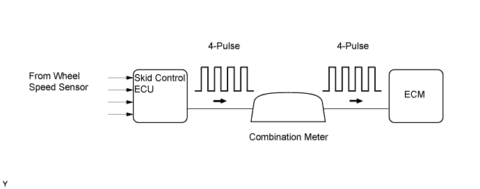
Vehicles, which are equipped with ABS (Anti-lock Brake System), detect the vehicle speed using the skid control ECU and wheel speed sensor. The wheel speed sensor monitors the wheel rotation speed and sends a signal to the skid control ECU. The skid control ECU converts the wheel speed signal into a 4- pulse signal and transmits it to the ECM via the combination meter. The ECM determines the vehicle speed based on the frequency of the pulse signal.
| DTC Detection Drive Pattern | DTC Detection Condition | Trouble Area |
|---|---|---|
| Vehicle is driven with engine at high load | Vehicle speed exceeds threshold (2 trip detection logic) |
|
| DTC No. | Data List |
|---|---|
| P0503 |
|
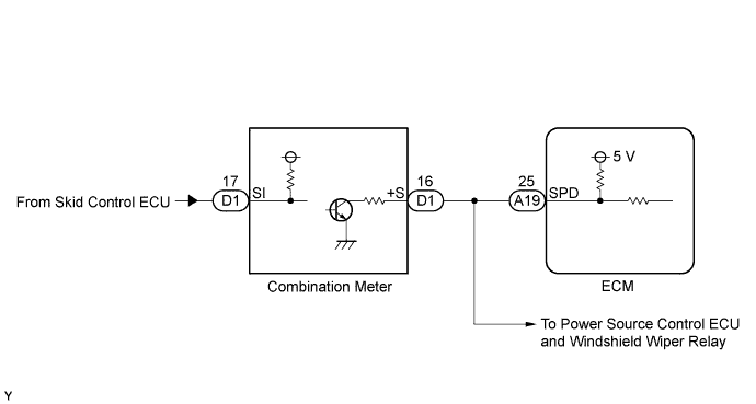
WIRING DIAGRAM
INSPECTION PROCEDURE
Note
When replacing the ECM, the ECM needs Registration and Initialization Click here.
Tech Tips
-
When the ECM must be replaced, before replacing the ECM, perform the "Learning Values Save" function using the intelligent tester. Then after installing the new ECM, perform all of the initializations/registrations for the "Learning Values Write" function by following the instructions shown on the tester display.
-
Read freeze frame data using the intelligent tester. Freeze frame data records the engine condition when malfunctions are detected. When troubleshooting, freeze frame data can help determine if the vehicle was moving or stationary, if the engine was warmed up or not, and other data from the time the malfunction occurred.
PROCEDURE
-
CHECK OPERATION OF SPEEDOMETER
-
Drive the vehicle and check whether the operation of the speedometer in the combination meter is normal.
Tech Tips
If the speedometer reading is normal, the vehicle speed sensor is operating normally.
OK The vehicle speed sensor is operating normally.
NG 
GO TO SPEEDOMETER MALFUNCTION Click here
OK 
-
-
READ VALUE USING INTELLIGENT TESTER (VEHICLE SPEED)
-
Connect the intelligent tester to the DLC3.
-
Turn the ignition switch to ON and turn the tester on.
-
Enter the following menus: Powertrain / Engine and ECT / Data List / Vehicle Speed.
-
Drive the vehicle.
-
Read the value displayed on the tester.
OK Vehicle speeds displayed on the tester and the speedometer display are equal.
NG 
CHECK HARNESS AND CONNECTOR (+S VOLTAGE) Click here
OK 
CHECK FOR INTERMITTENT PROBLEMS Click here
-
-
CHECK HARNESS AND CONNECTOR (+S VOLTAGE)
-
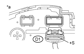
Text in Illustration *a Rear view of wire harness connector
(to Combination Meter)
Disconnect the combination meter connector.
-
Measure the voltage according to the value(s) in the table below.
Standard Voltage Tester Connection Switch Condition Specified Condition D1-16 (+S) - Body ground Ignition switch ON 4.5 to 5.5 V -
Reconnect the combination meter connector.
NG
CHECK HARNESS AND CONNECTOR (COMBINATION METER ASSEMBLY - ECM) Click here
OK
-
-
CHECK COMBINATION METER ASSEMBLY (SPD SIGNAL WAVEFORM)
-
Move the shift lever to N.
-
Jack up the vehicle.
-
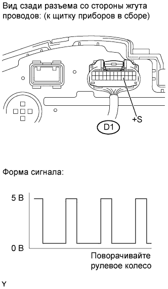
Check the voltage between the terminal of the combination meter and the body ground while a wheel is turned slowly.
Standard Voltage Tester Connection Switch Condition Specified Condition D1-16 (+S) - Body ground Ignition switch ON
Turn wheel slowly
Voltage generate intermittently Tech Tips
The output voltage should fluctuate up and down, similarly to the diagram, when the wheel is turned slowly.
NG
REPLACE COMBINATION METER ASSEMBLY Click here
OK
-
-
CHECK HARNESS AND CONNECTOR (COMBINATION METER ASSEMBLY - ECM)
-
Disconnect the combination meter connector.
-
Disconnect the ECM connector.
-
Measure the resistance according to the value(s) in the table below.
Standard Resistance (Check for Open) Tester Connection Condition Specified Condition D1-16 (+S) - A19-25 (SPD) Always Below 1 Ω Standard Resistance (Check for Short) Tester Connection Condition Specified Condition D1-16 (+S) or A19-25 (SPD) - Body ground Always 10 kΩ or higher -
Reconnect the combination meter connector.
-
Reconnect the ECM connector.
NG
REPAIR OR REPLACE HARNESS OR CONNECTOR Click here
OK
-
-
REPLACE ECM
-
Replace the ECM Click here.
NEXT
CONFIRM WHETHER MALFUNCTION HAS BEEN SUCCESSFULLY REPAIRED Click here
-
-
REPAIR OR REPLACE HARNESS OR CONNECTOR
NEXT
CONFIRM WHETHER MALFUNCTION HAS BEEN SUCCESSFULLY REPAIRED Click here
-
REPLACE COMBINATION METER ASSEMBLY
-
Replace the combination meter assembly Click here.
NEXT
-
-
CONFIRM WHETHER MALFUNCTION HAS BEEN SUCCESSFULLY REPAIRED
-
Connect the intelligent tester to the DLC3.
-
Clear the DTCs Click here.
-
Turn the ignition switch off and wait for 30 seconds or more.
-
Start the engine.
-
Drive the vehicle with the engine at high load and in high gear.
-
Confirm that the DTC is not output again.
NEXT
END
-