СИСТЕМА ECD, Diagnostic DTC:P0031, P0032
| DTC Code | DTC Name |
|---|---|
| P0031 | Oxygen (A/F) Sensor Heater Control Circuit Low (Bank 1 Sensor 1) |
| P0032 | Oxygen (A/F) Sensor Heater Control Circuit High (Bank 1 Sensor 1) |
DESCRIPTION
In order to obtain high purification rates for the carbon monoxide (CO) and hydrocarbon (HC) and a high collection/oxidization rate for particulate matter (PM) in the exhaust gas, a CCo + DPF catalytic converter is used. The air fuel ratio sensor is used to compensate for variation in the EGR rate to reduce PM accumulation of the DPF catalytic converter.
The A/F sensor provides an output voltage that is proportional to the air-fuel ratio that it is measuring. The A/F sensor output voltage is used as feedback to allow the ECM to control the A/F mixture. The inner surface of the air fuel ratio sensor element is exposed to outside air. The outer surface of the sensor element is exposed to exhaust gases. The sensor element is made of platinum coated zirconia and includes an integrated heating element. The zirconia element generates a small voltage when there is a large difference in the oxygen concentrations of the exhaust and the outside air. The platinum coating amplifies the voltage generation. When heated, the sensor becomes very efficient. If the temperature of the exhaust is low, the sensor will not generate useful voltage signals without supplemental heating. The ECM regulates the supplemental heating by using a duty-cycle approach to regulate the average current in the heater element.
| DTC Detection Drive Pattern | DTC Detection Condition | Trouble Area |
|---|---|---|
| 5 minutes elapsed after engine coolant temperature reaches more than 70°C (158°F) | Ground short or open in air fuel ratio sensor heater circuit for 5 seconds or more (1 trip detection logic) |
|
| DTC Detection Drive Pattern | DTC Detection Condition | Trouble Area |
|---|---|---|
| 5 minutes elapsed after engine coolant temperature reaches more than 70°C (158°F) | Battery short in air fuel ratio sensor heater circuit for 5 seconds or more (1 trip detection logic) |
|
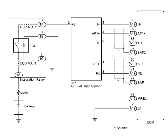
WIRING DIAGRAM
INSPECTION PROCEDURE
Note
-
When replacing the ECM and/or air fuel ratio sensor, the ECM needs Registration and Initialization Click here.
-
Inspect the fuses for circuits related to this system before performing the following inspection procedure.
Tech Tips
-
When the ECM must be replaced, before replacing the ECM, perform the "Learning Values Save" function using the intelligent tester. Then after installing the new ECM, perform all of the initializations/registrations for the "Learning Values Write" function by following the instructions shown on the tester display.
-
Read freeze frame data using the intelligent tester. Freeze frame data records the engine condition when malfunctions are detected. When troubleshooting, freeze frame data can help determine if the vehicle was moving or stationary, if the engine was warmed up or not, and other data from the time the malfunction occurred.
PROCEDURE
-
INSPECT AIR FUEL RATIO SENSOR (HEATER RESISTANCE)
-
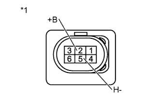
Text in Illustration *1 Component without harness connected
(Air Fuel Ratio Sensor)
Disconnect the air fuel ratio sensor connector.
-
Measure the resistance according to the value(s) in the table below.
Standard Resistance Tester Connection Condition Specified Condition 2 (+B) - 5 (H-) 20°C 2.0 to 5.0 Ω -
Reconnect the air fuel ratio sensor connector.
NG 
REPLACE AIR FUEL RATIO SENSOR Click here
OK 
-
-
CHECK HARNESS AND CONNECTOR (POWER SOURCE)
-
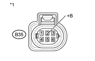
Text in Illustration *1 Front view of wire harness connector
(to Air Fuel Ratio Sensor)
Disconnect the air fuel ratio sensor connector.
-
Measure the voltage according to the value(s) in the table below.
Standard Voltage Tester Connection Switch Condition Specified Condition B35-2 (+B) - Body ground Ignition switch ON 11 to 14 V -
Reconnect the air fuel ratio sensor connector.
NG
CHECK HARNESS AND CONNECTOR (AIR FUEL RATIO SENSOR - INTEGRATION RELAY) Click here
OK
-
-
CHECK HARNESS AND CONNECTOR (AIR FUEL RATIO SENSOR - ECM)
-
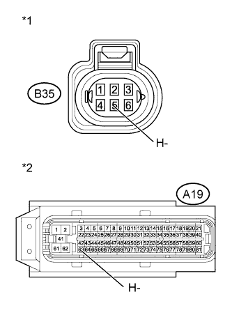
Text in Illustration *1 Front view of wire harness connector
(to Air Fuel Ratio Sensor)
*2 Front view of wire harness connector
(to ECM)
Disconnect the air fuel ratio sensor connector.
-
Disconnect the ECM connector.
-
Measure the resistance according to the value(s) in the table below.
Standard Resistance (Check for Open) Tester Connection Condition Specified Condition B35-5 (H-) - A19-63 (H-) Always Below 1 Ω Standard Resistance (Check for Short) Tester Connection Condition Specified Condition B35-5 (H-) or A19-63 (H-) - Body ground Always 10 kΩ or higher -
Reconnect the air fuel ratio sensor connector.
-
Reconnect the ECM connector.
NG
REPAIR OR REPLACE HARNESS OR CONNECTOR Click here
OK
-
-
REPLACE ECM
-
Replace the ECM Click here.
NEXT
CONFIRM WHETHER MALFUNCTION HAS BEEN SUCCESSFULLY REPAIRED Click here
-
-
CHECK HARNESS AND CONNECTOR (AIR FUEL RATIO SENSOR - INTEGRATION RELAY)
-
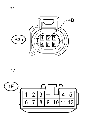
Text in Illustration *1 Front view of wire harness connector
(to Air Fuel Ratio Sensor)
*2 Front view of wire harness connector
(to Integration Relay)
Disconnect the air fuel ratio sensor connector.
-
Disconnect the integration relay connector.
-
Measure the resistance according to the value(s) in the table below.
Standard Resistance (Check for Open) Tester Connection Condition Specified Condition B35-2 (+B) - 1F-8 Always Below 1 Ω Standard Resistance (Check for Short) Tester Connection Condition Specified Condition B35-2 (+B) or 1F-8 - Body ground Always 10 kΩ or higher -
Reconnect the air fuel ratio sensor connector.
-
Reconnect the integration relay connector.
NG
REPAIR OR REPLACE HARNESS OR CONNECTOR Click here
OK
-
-
CHECK ECM POWER SOURCE CIRCUIT
-
Check the ECM power source circuit Click here.
NEXT
CONFIRM WHETHER MALFUNCTION HAS BEEN SUCCESSFULLY REPAIRED Click here
-
-
REPLACE AIR FUEL RATIO SENSOR
-
Replace the air fuel ratio sensor Click here.
-
Perform the A/F Sensor Compensation Reset Click here.
NEXT
CONFIRM WHETHER MALFUNCTION HAS BEEN SUCCESSFULLY REPAIRED Click here
-
-
REPAIR OR REPLACE HARNESS OR CONNECTOR
NEXT
-
CONFIRM WHETHER MALFUNCTION HAS BEEN SUCCESSFULLY REPAIRED
-
Connect the intelligent tester to the DLC3.
-
Clear the DTCs Click here.
-
Start the engine and warm it up until the engine coolant temperature reaches 70°C or more.
-
Allow the engine to idle for 5 minutes or more.
-
Enter the following menus: Powertrain / Engine and ETC / DTC.
-
Confirm that the DTC is not output again.
NEXT 
END
-