BLOWER RESISTOR (for Manual Air Conditioning System) REMOVAL

CAUTION:
Some of these service operations affect the SRS airbag system. Read the precautionary notices concerning the SRS airbag system before servicing Click here.
-
DISCONNECT CABLE FROM NEGATIVE BATTERY TERMINAL
CAUTION:
Wait at least 90 seconds after disconnecting the cable from the negative (-) battery terminal to disable the SRS system.
-
REMOVE CENTER LOWER INSTRUMENT CLUSTER FINISH PANEL
-
Disengage the 6 clips and remove the center lower instrument cluster finish panel.
-
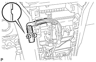
Disconnect the 2 connectors.
-
Disengage the 2 claws and disconnect the heater control cable, then remove the center lower instrument cluster finish panel.
-
-
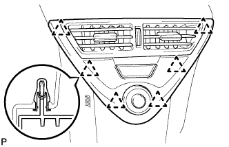
REMOVE CENTER NO. 1 INSTRUMENT CLUSTER FINISH PANEL
-
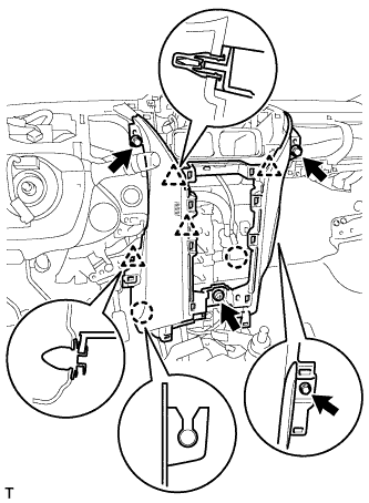
Remove the 2 bolts.
-
Disengage the 6 clips.
-
Disconnect the all connectors and remove the center No. 1 instrument cluster finish panel.
-
-
REMOVE SHIFT LEVER KNOB SUB-ASSEMBLY (for CVT)
-
Remove the shift lever knob from the shift lever.
-
-
REMOVE SHIFT LEVER KNOB SUB-ASSEMBLY (for Manual Transaxle)
-
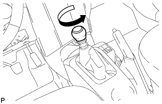
Turn the shift lever knob counterclockwise and remove the shift lever knob.
-
-
REMOVE CONSOLE UPPER PANEL SUB-ASSEMBLY (for CVT)
-
Disengage the 8 claws and remove the console upper panel.
-
-
REMOVE CONSOLE UPPER PANEL SUB-ASSEMBLY (for Manual Transaxle)
-
Disengage the 8 claws and remove the console upper panel.
-
Separate the shifting hole cover.
-
-
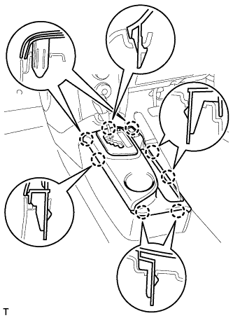
REMOVE REAR CONSOLE BOX ASSEMBLY
-
Rotate the 2 rear clips in the direction indicated by the arrows and remove them.
-
Disengage the 2 front clips and remove the rear console box assembly RR.
-
-
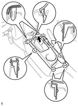
REMOVE FRONT CONSOLE BOX COVER
-
Disengage the 2 claws and 4 clips and remove the front console box cover.
-
-
REMOVE LOWER CENTER INSTRUMENT CLUSTER FINISH PANEL SUB-ASSEMBLY
-
Disengage the 8 clips.
-
Disconnect the all connectors.
-
Disengage the 2 claws and disconnect the No. 2 heater control cable.
-
Disengage the 2 claws and disconnect the air mix damper control cable.
-
-
REMOVE FRONT DOOR SCUFF PLATE RH
-
Disengage the 9 claws and remove the front door scuff plate.
-
-
REMOVE FRONT DOOR SCUFF PLATE LH
Tech Tips
Use the same procedure as for the RH side.
-
SEPARATE FRONT DOOR OPENING TRIM WEATHERSTRIP RH
-
SEPARATE FRONT DOOR OPENING TRIM WEATHERSTRIP LH
-
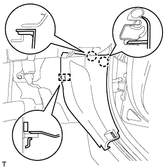
REMOVE COWL SIDE TRIM BOARD RH
-
Disengage the 2 claws and guide and remove the cowl side trim board.
-
-
REMOVE COWL SIDE TRIM BOARD LH
Tech Tips
Use the same procedure as for the RH side.
-
REMOVE LOWER NO. 2 INSTRUMENT PANEL FINISH PANEL
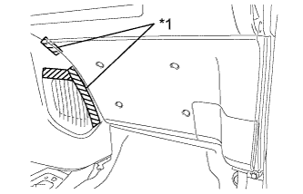
Text in Illustration *1 Protective Tape
-
Apply protective tape, as shown in the illustration.
-
Remove the <C> bolt.
-
Disengage the 4 claws and 2 clips and remove the lower No. 2 instrument panel finish panel.
-
-
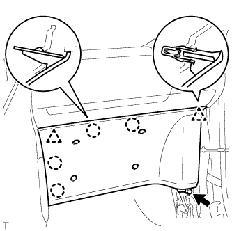
REMOVE LOWER NO. 1 INSTRUMENT PANEL FINISH PANEL
-
Remove the 2 <C> bolts.
-
Disengage the 2 claws and the 7 clips and separate the lower No. 1 instrument panel finish panel.
-
Disconnect the connector.
-
Disengage the 2 claws and disconnect the DLC3 connector.
-
Disengage the 3 claws and disconnect the hood lock control lever.
-
-
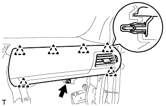
REMOVE LOWER NO. 1 INSTRUMENT PANEL AIR BAG ASSEMBLY
-
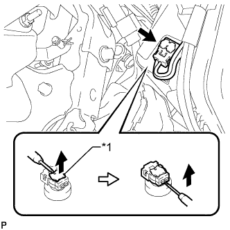
Text in Illustration *1 Locking Button Using a thin-bladed screwdriver, release the locking button.
-
Using a thin-bladed screwdriver, disconnect the airbag connector and remove the instrument panel wire.
-
Remove the 3 bolts.
-
Disengage the 2 guides and remove the knee airbag assembly.
-
-
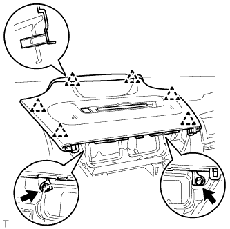
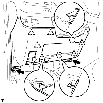
REMOVE UPPER INSTRUMENT PANEL SUB-ASSEMBLY
-
Remove the <F> bolt.
-
Disengage the 6 clips and remove the upper instrument panel.
-
-
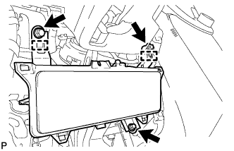
REMOVE INSTRUMENT CLUSTER FINISH NO. 1 PANEL
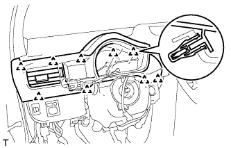
-
Disengage the 9 clips and remove the instrument cluster finish No. 1 panel.
-
-
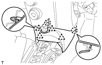
REMOVE NO. 3 AIR DUCT SUB-ASSEMBLY
-
Disconnect the connector.
Tech Tips
If the vehicle is equipped with stop and start system, disconnect the connector.
-
Remove the clip.
-
Disengage the 3 claws and remove the air duct.
-
-
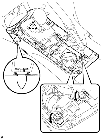
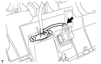
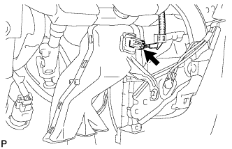
REMOVE ROOM TEMPERATURE SENSOR (COOLER THERMISTOR)
-
Disengage the 2 claws and remove the room temperature sensor.
-
Disconnect the connector.
-
-
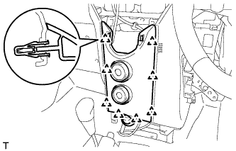
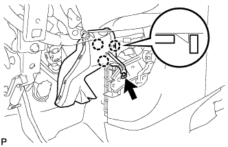
REMOVE LOWER INSTRUMENT PANEL
-
Remove the 3 <F> bolts and <E> screw.
-
Disengage the 2 claws and 4 clips and remove the lower instrument panel.
-
-
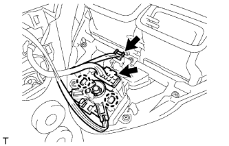
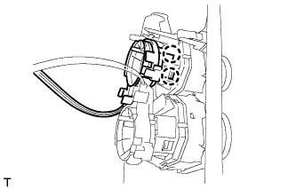
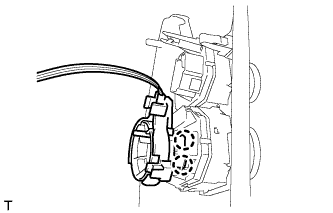
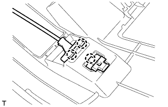
REMOVE BLOWER RESISTOR
-
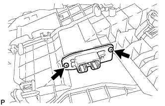
Disconnect the connector.
-
Remove the 2 screws and blower resister.
-