COMPRESSOR (for 1ND-TV) INSTALLATION

-
ADJUST COMPRESSOR OIL
-
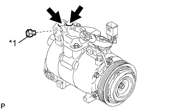
Text in Illustration *1 Drain bolt (Washer) When replacing the compressor with a new one, gradually discharge the refrigerant gas from the service valve. Then drain the following amount of oil from the new compressor before installation, so that the amount of oil contained in it is the same as that in the compressor to be replaced.
Tech Tips
New compressors are filled with sufficient oil for the whole cycle. Therefore, it is necessary to drain residual oil from the condenser and cooling unit.
Standard (The amount of oil inside a new cooler compressor assembly: 100 (+15) cc) - (The amount of oil remaining in the removed cooler compressor assembly A + oil remaining in the reserve chamber: 45 cc) = (The amount of oil to be removed when replacing the compressor) Note
-
When A+45 cc exceeds the standard oil fill volume specified for the cooler compressor assembly by part number, install the compressor without adjusting the oil volume.
Example:
If A = 60 cc, A+45 cc = 105 cc. If the standard volume is 100 cc, install the cooler compressor as is.
-
When checking the compressor oil level, observe the precautions for cooler removal/ installation.
-
If a new compressor is installed without removing the same amount of oil as is remaining in the vehicle pipes, the amount of oil will be too large. This prevents heat exchange in the refrigerant cycle and will cause a refrigeration failure.
-
If the amount of oil remaining in the removed compressor is too low, check for an oil leak.
-
Use ND-OIL8 or equivalent for compressor oil.
-
-
If draining the oil is difficult, drain the oil using the following procedure:
-
Remove the suction seal cap.
-
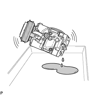
Lightly shake the compressor with the suction port facing down, and drain the oil (*1).
Note
Do not allow the pulley to come into contact with the compressor oil.
-
-
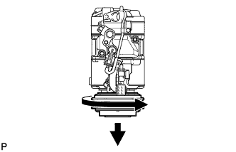
With the DL pulley facing down, rotate the pulley in the direction shown by the arrow 10 times at a rate of approximately once every 2 seconds (*2).
Note
If the pulley is rotated, refrigerant or oil might splash out. Thus, keep your face away from the compressor port.
-
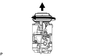
Rotate the pulley once in the direction shown by the arrow while quickly turning the compressor so the pulley is up (*3).
-
Proceed with the above procedure (*1) and drain the oil (*4).
-
Drain the oil by repeating the procedures above approximately 5 times (from (*2) to (*4)).
-
-
INSTALL COOLER COMPRESSOR ASSEMBLY
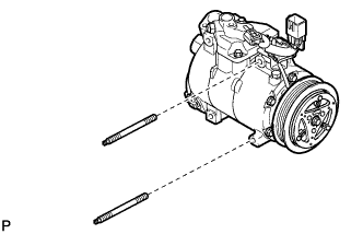
-
Using a "TORX" socket wrench (E8), install the compressor with the 2 stud bolts.
- Torque:
- 15 N*m { 153 kgf*cm, 11 ft.*lbf }
-
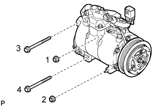
Install the compressor with the 2 bolts and the 2 nuts.
- Torque:
- 25 N*m { 250 kgf*cm, 18 ft.*lbf }
Tech Tips
Tighten the bolts and the nuts in the order shown in the illustration.
-
Connect the connector.
-
-
CONNECT SUCTION HOSE SUB-ASSEMBLY
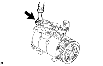
-
Remove the attached vinyl tape from the suction hose.
-
Sufficiently apply compressor oil to a new O-ring and the fitting surface of the cooler compressor.
Compressor oil ND-OIL 8 or equivalent -
Install the O-ring onto the suction hose.
-
Connect the suction hose to the cooler compressor with the bolt.
- Torque:
- 9.8 N*m { 100 kgf*cm, 87 in.*lbf }
-
-
CONNECT DISCHARGE HOSE SUB-ASSEMBLY
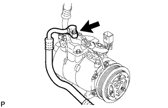
-
Remove the attached vinyl tape from the discharge hose.
-
Sufficiently apply compressor oil to a new O-ring and the fitting surface of the cooler compressor.
Compressor oil ND-OIL 8 or equivalent -
Install the O-ring onto the discharge hose.
-
Connect the discharge hose to the cooler compressor with the bolt.
- Torque:
- 9.8 N*m { 100 kgf*cm, 87 in.*lbf }
-
-
INSTALL FRONT FRAME ASSEMBLY
-
Install the front frame assembly Click here.
-
-
INSTALL V (COOLER COMPRESSOR TO CRANKSHAFT PULLEY) BELT NO. 1
-
Install the V (cooler compressor to crankshaft pulley) belt No. 1 Click here.
-
-
CHARGE REFRIGERANT
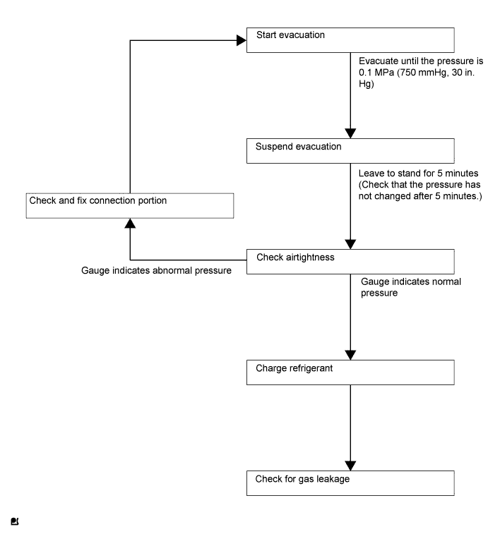
Tech Tips
Charge refrigerant in accordance with the equipment manual.
-
Perform vacuum purging using a vacuum pump.
-
Charge refrigerant HFC-134a (R134a).
- SST
- 09985-20010 ( 09985-02010, 09985-02050, 09985-02060, 09985-02070, 09985-02080, 09985-02090, 09985-02110, 09985-02130, 09985-02140, 09985-02150 )
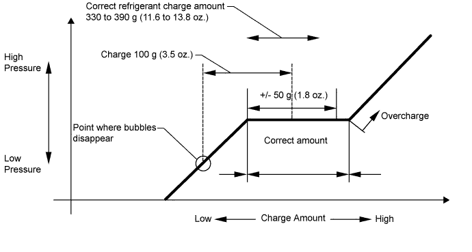
Standard 330 to 390 g (11.6 to 13.8 oz.) Note
-
Do not start the engine before charging it with refrigerant as the cooler compressor does not work properly without sufficient refrigerant. This could cause the compressor to overheat.
-
Approximately 100 g (3.5 oz.) of refrigerant may need to be charged after bubbles disappear.
The volume of refrigerant should be measured, not checked with the sight glass.
Tech Tips
-
The relationship between the refrigerant charge amount and the pressure is as follows.
-
High Charge Range:
If the refrigerant is overcharged, the pressure rises on the high-pressure side. High-pressure cut off frequently occurs. This causes insufficient cooling performance and also insufficient compressor lubrication.
-
Low Charge Range:
A shortage of refrigerant causes insufficient cooling performance and low circulation of refrigerant oil, which shortens the compressor life. Operation with insufficient coolant raises the refrigerant temperature and causes heat deterioration of the rubber seals and hoses. Cracking and subsequent refrigerant leakage may occur.
-
Install the caps onto the service valves on the refrigerant line.
-
-
WARM UP ENGINE
Note
Warm up the engine at less than 2000 rpm for 1 minute or more after charging it with refrigerant.
-
INSPECT FOR REFRIGERANT LEAK
-
After recharging the refrigerant gas, check for refrigerant gas leakage using a halogen leak detector.
-
Perform the operation as follows:
-
Stop the engine.
-
Secure good ventilation (the halogen leak detector may react to volatile gases other than refrigerant, such as evaporated gasoline or exhaust gas).
-
Repeat the test 2 or 3 times.
-
Make sure that some refrigerant remains in the refrigeration system.
When the compressor is off: approximately 392 to 588 kPa (4 to 6 kgf/cm2, 57 to 85 psi)
Tech Tips
It is impossible for the above pressure to be maintained if there is leakage.
-
-
Using the halogen leak detector, check the refrigerant line, especially at the connection points, for leakage.
-
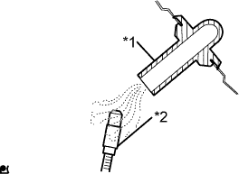
Text in illustration *1 Drain hose *2 Halogen leak detector Bring the halogen leak detector close to the drain hose before performing the test.
Tech Tips
-
After the blower motor has stopped, leave the cooling unit for at least 15 minutes.
-
Place the halogen leak detector sensor under the drain hose.
-
When bringing the halogen leak detector close to the drain hose, make sure that the halogen leak detector does not react to other volatile gases.
If such a reaction is unavoidable, the vehicle must be lifted up.
-
-
If no gas leakage is detected from the drain hose, remove the blower motor from the cooling unit. Insert the halogen leak detector sensor into the unit and perform the test.
-
Disconnect the pressure switch connector and leave it for approximately 20 minutes. Bring the halogen leak detector close to the pressure switch and perform the test.
-