AIR CONDITIONING UNIT INSTALLATION

-
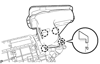
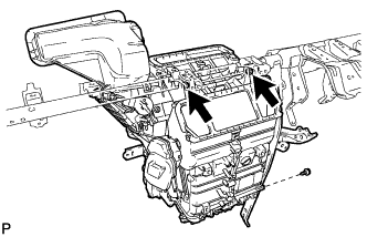
INSTALL NO. 4 AIR DUCT SUB-ASSEMBLY
-
Engage the 4 claws and install the air duct.
-
-
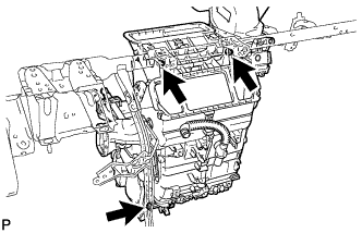
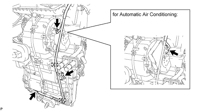
INSTALL AIR CONDITIONING UNIT ASSEMBLY (for LHD)
-
Install the air conditioning onto the instrument panel reinforcement with the 2 bolts and screw.
- Torque:
- 4.0 N*m { 41 kgf*cm, 35 in.*lbf, for bolt }
-
For vehicles with the PTC assembly, tighten the ground wire bolt.
- Torque:
- 8.0 N*m { 82 kgf*cm, 71 in.*lbf }
-
-
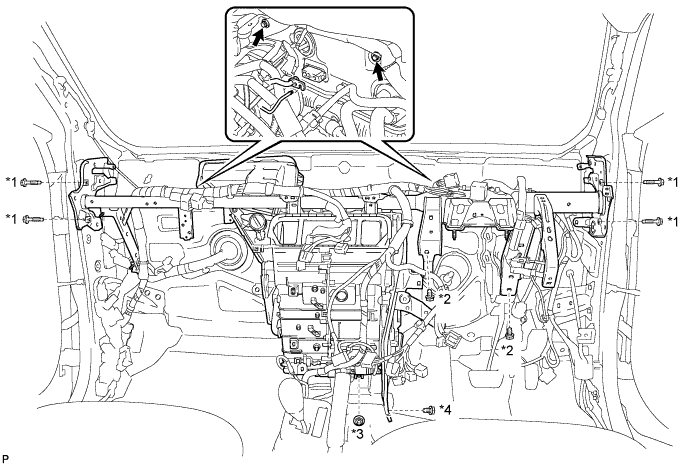
INSTALL INSTRUMENT PANEL REINFORCEMENT ASSEMBLY (for LHD)
-
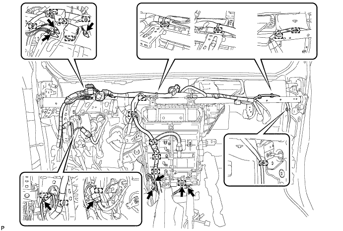
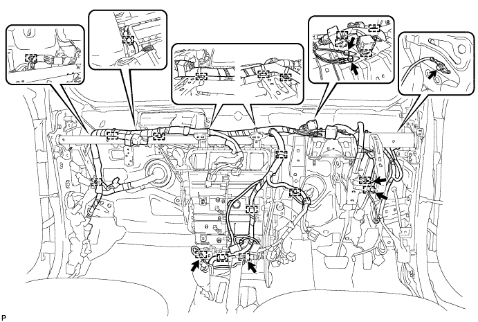
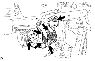
Connect the connectors and clamps behind the air conditioner unit.
-
Install the instrument panel reinforcement with air conditioning unit with the 9 bolts and nut.
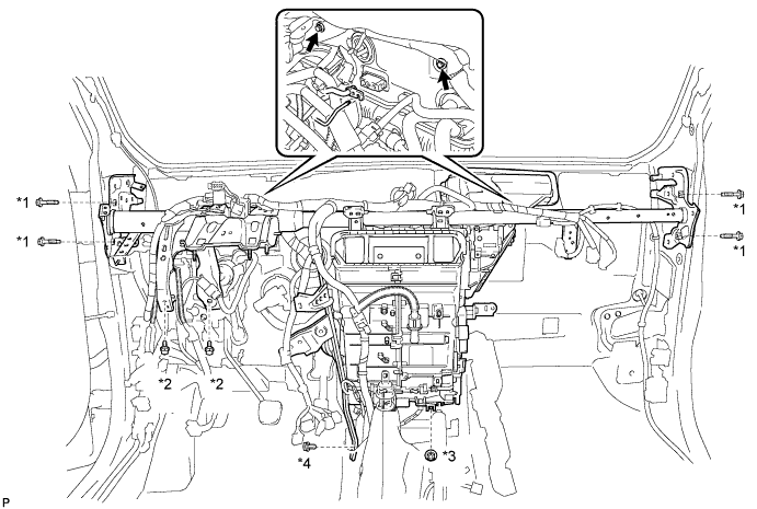
- Torque:
- 32 N*m { 326 kgf*cm, 24 ft.*lbf, for bolt *1 }
- Torque:
- 24 N*m { 245 kgf*cm, 18 ft.*lbf, for bolt *2 }
- Torque:
- 9.8 N*m { 100 kgf*cm, 87 in.*lbf, for nut *3 }
- Torque:
- 2.5 N*m { 25 kgf*cm, 22 in.*lbf, for bolt *4 }
-
Connect the connectors.
-
Engage the clamps.
-
Tighten the ground wire bolts.
- Torque:
- 8.4 N*m { 85 kgf*cm, 86 in.*lbf }
-
-
INSTALL AIR CONDITIONING UNIT ASSEMBLY (for RHD)
-
Install the air conditioning onto the instrument panel reinforcement with the 2 bolts and screw.
- Torque:
- 4.0 N*m { 41 kgf*cm, 35 in.*lbf, for bolt }
-
For vehicles with the PTC assembly, tighten the ground wire bolt.
- Torque:
- 8.0 N*m { 82 kgf*cm, 71 in.*lbf }
-
-
INSTALL INSTRUMENT PANEL REINFORCEMENT ASSEMBLY (for RHD)
-
Connect the connectors and clamps behind the air conditioner unit.
-
Install the instrument panel reinforcement with air conditioning unit with the 9 bolts and nut.
- Torque:
- 32 N*m { 326 kgf*cm, 24 ft.*lbf, for bolt *1 }
- Torque:
- 24 N*m { 245 kgf*cm, 18 ft.*lbf, for bolt *2 }
- Torque:
- 9.8 N*m { 100 kgf*cm, 87 in.*lbf, for nut *3 }
- Torque:
- 2.5 N*m { 25 kgf*cm, 22 in.*lbf, for bolt *3 }
-
Connect the connectors.
-
Engage the clamps.
-
Tighten the ground wire bolts.
- Torque:
- 8.4 N*m { 85 kgf*cm, 86 in.*lbf }
-
-
INSTALL INSTRUMENT PANEL JUNCTION BLOCK ASSEMBLY
-
Connect the connectors on the back side.
-
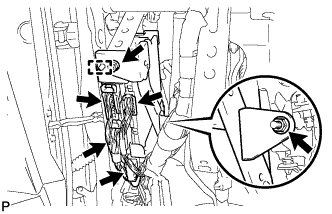
Engage the guide and install the instrument panel junction block with the 2 nuts.
- Torque:
- 5.4 N*m { 55 kgf*cm, 48 in.*lbf }
-
Connect the connectors on the front side.
-
-
INSTALL DOUBLE LOCK DOOR CONTROL RELAY ASSEMBLY (w/ Double Locking System)
-
Install the double lock door control relay with the screw.
-
Connect the connector.
-
-
INSTALL WINDSHIELD WIPER RELAY ASSEMBLY (w/ Rain Sensor)
-
Install the windshield wiper relay with the screw.
-
Connect the connector.
-
-
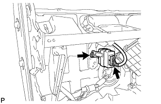
INSTALL ECU INTEGRATION BOX RH (for LHD)
-
Install the ECU integration box with 2 screws.
-
Connect the connectors.
-
-
INSTALL ECU INTEGRATION BOX LH (for RHD)
-
Install the ECU integration box with 2 screws.
-
Connect the connectors.
-
-
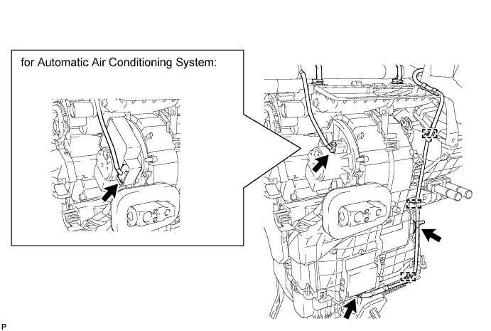
INSTALL HEATER WATER OUTLET HOSE

-
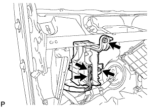
Install the heater water outlet hose onto the heater unit.
Tech Tips
Perform the installation with the hose clip and mark at the correct angle.
-
-
INSTALL HEATER WATER INLET HOSE
-
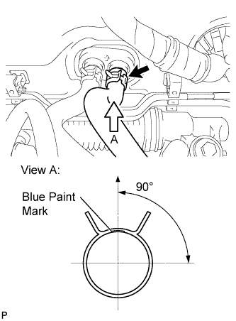
Install the heater water inlet hose onto the heater unit.
Tech Tips
Perform the installation with the hose clip and mark at the correct angle.
-
-
INSTALL AIR CONDITIONING TUBE ASSEMBLY
-
Remove the vinyl tape from air conditioning tube and the connecting portion of the unit.
-
Apply sufficient compressor oil (ND-OIL8) to a new O-ring and the connecting part of the air conditioning tube.
Capacity oil ND-OIL8 or equivalent -
Install the O-ring onto the air conditioning tube.
-
Connect the air conditioning tube to the unit.
-
-
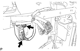
INSTALL SUCTION PIPE SUB-ASSEMBLY
-
Remove the vinyl tape from suction pipe and the connecting portion of the unit.
-
Apply sufficient compressor oil (ND-OIL8) to a new O-ring and the connecting part of the suction pipe.
Capacity oil ND-OIL8 or equivalent -
Install the O-ring onto the suction pipe.
-
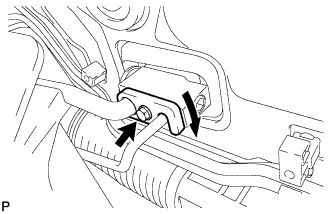
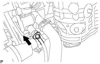
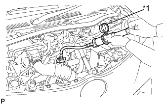
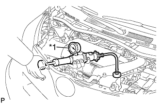
Turn the hook connector in the direction indicated by the arrow in the illustration.
-
Insert the pipe joints securely into the fitting holes and tighten the bolt.
- Torque:
- 9.8 N*m { 100 kgf*cm, 87 in.*lbf }
-
-
INSTALL STEERING COLUMN ASSEMBLY
-
Install the steering column assembly Click here.
-
-
INSTALL INSTRUMENT PANEL SUB-ASSEMBLY
-
Install the instrument panel sub-assembly Click here.
-
-
INSTALL WINDSHIELD WIPER MOTOR AND LINK ASSEMBLY
-
Install the windshield wiper motor and link assembly Click here.
-
-
ADD ENGINE COOLANT (for 1KR-FE)
-
Tighten the water inlet drain cock plug.
-
Plunge the engine drain cock plug.
-
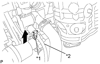
Text in Illustration *1 Water Inlet Clip *2 Hose Install the water inlet clip.
-
Disconnect the hose from the water inlet drain cock plug.
-
Slowly fill the radiator with TOYOTA Super Long Life Coolant (SLLC).
Standard Capacity Item Capacity for Manual Transaxle 4.3 liters (4.5 US qts, 3.8 Imp. qts) for CVT 4.5 liters (4.8 US qts, 4.0 Imp. qts) Note
Never use water as a substitute for engine coolant.
Tech Tips
TOYOTA vehicles are filled with TOYOTA SLLC at the factory. In order to avoid damage to the engine cooling system and other technical problems, only use TOYOTA SLLC or similar high quality ethylene glycol based non-silicate, non-amine, non-nitrite, non-borate coolant with long-life hybrid organic acid technology (coolant with long-life hybrid organic acid technology is a combination of low phosphates and organic acids).
-
Squeeze the inlet and outlet radiator hoses several times by hand, and then check the level of the coolant.
If the coolant level is low, add coolant.
-
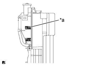
Text in Illustration *a FULL Line Fill the radiator reserve tank with coolant to the FULL level.
-
Install the water filler cap sub-assembly.
-
Start the engine and warm it up.
-
Bleed air from the cooling system.
Note
-
Before starting the engine, turn the A/C switch off.
-
Adjust the air conditioning temperature setting to MAX (HOT).
-
Adjust the air conditioning blower setting to LO.
-
Warm up the engine until the thermostat opens. While the thermostat is open, allow the coolant to circulate for several minutes.
Tech Tips
Thermostat opening timing can be determined by squeezing the inlet radiator hose, and sensing vibrations when the engine coolant starts to flow inside the hose.
CAUTION:
When squeezing the radiator hoses:
-
Wear protective gloves.
-
Be careful as the radiator hoses are hot.
-
Keep your hands away from the radiator fan.
-
-
-
Stop the engine, and wait until the engine coolant cools down.
-
Remove the water filler cap sub-assembly and check the coolant level.
If the coolant level is below the LOW line, repeat all of the procedures above.
-
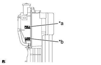
Text in Illustration *a FULL Line *b LOW Line When the coolant level stops going down, check that the coolant level is between the FULL and LOW lines.
If the coolant level is low, add coolant to the reservoir tank FULL line.
-
-
ADD ENGINE COOLANT (for 1ND-TV)
-
If the vehicle is equipped with combustion type power heater Click here.
-
If the vehicle is not equipped with combustion type power heater Click here.
-
-
CONNECT CABLE TO NEGATIVE BATTERY TERMINAL
- Torque:
- 5.4 N*m { 55 kgf*cm, 48 in.*lbf }
-
INSPECT SRS WARNING LIGHT
-
Inspect the SRS warning light Click here.
-
-
CHARGE REFRIGERANT
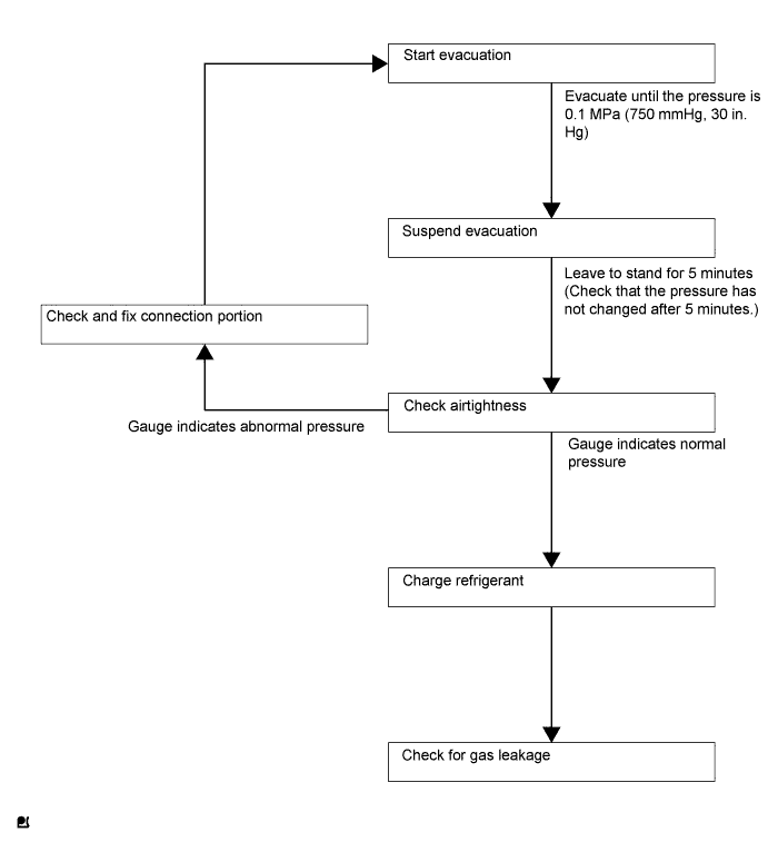
Tech Tips
Charge refrigerant in accordance with the equipment manual.
-
Perform vacuum purging using a vacuum pump.
-
Charge refrigerant HFC-134a (R134a).
- SST
- 09985-20010 ( 09985-02010, 09985-02050, 09985-02060, 09985-02070, 09985-02080, 09985-02090, 09985-02110, 09985-02130, 09985-02140, 09985-02150 )
Standard 330 to 390 g (11.6 to 13.8 oz.) Note
-
Do not start the engine before charging it with refrigerant as the cooler compressor does not work properly without sufficient refrigerant. This could cause the compressor to overheat.
-
Approximately 100 g (3.5 oz.) of refrigerant may need to be charged after bubbles disappear.
The volume of refrigerant should be measured, not checked with the sight glass.
Tech Tips
-
The relationship between the refrigerant charge amount and the pressure is as follows.
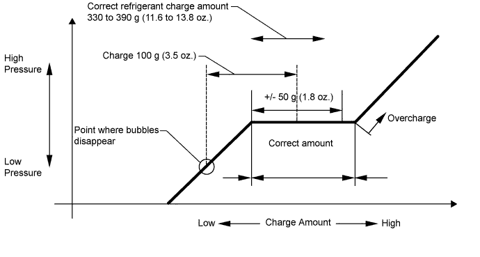
-
High Charge Range:
If the refrigerant is overcharged, the pressure rises on the high-pressure side. High-pressure cut off frequently occurs. This causes insufficient cooling performance and also insufficient compressor lubrication.
-
Low Charge Range:
A shortage of refrigerant causes insufficient cooling performance and low circulation of refrigerant oil, which shortens the compressor life. Operation with insufficient coolant raises the refrigerant temperature and causes heat deterioration of the rubber seals and hoses. Cracking and subsequent refrigerant leakage may occur.
-
Install the caps onto the service valves on the refrigerant line.
-
-
WARM UP ENGINE
Note
Warm up the engine at less than 2000 rpm for 1 minute or more after charging it with refrigerant.
-
INSPECT FOR COOLANT LEAK (for 1KR-FE)
CAUTION:
To avoid the danger of being burned, do not remove the water filler cap sub-assembly while the engine and radiator assembly are still hot. Thermal expansion will cause hot engine coolant and steam to blow out from the radiator assembly.
-
Text in Illustration *1 Radiator Cap Tester Fill the radiator assembly with engine coolant, and attach a radiator cap tester.
-
Pump the tester to 118 kPa (1.2 kgf/cm2, 17.1 psi), and then check that the pressure does not drop.
If the pressure drops, check the hoses, radiator assembly and water pump assembly for leaks. If there are no signs or traces of external engine coolant leaks, check the heater core, cylinder block and head.
-
-
INSPECT FOR COOLANT LEAK (for 1ND-TV)
CAUTION:
To avoid the danger of being burned, do not remove the radiator cap sub-assembly while the engine and radiator assembly are still hot. Thermal expansion will cause hot engine coolant and steam to blow out from the radiator assembly.
-
Text in Illustration *1 Radiator Cap Tester Fill the radiator assembly with engine coolant, and attach a radiator cap tester.
-
Pump the tester to 118 kPa (1.2 kgf/cm2, 17.1 psi), and then check that the pressure does not drop.
If the pressure drops, check the hoses, radiator assembly and water pump assembly for leaks. If there are no signs or traces of external engine coolant leaks, check the heater core, cylinder block and head.
-
-
INSPECT FOR REFRIGERANT LEAK
-
After recharging the refrigerant gas, check for refrigerant gas leakage using a halogen leak detector.
-
Perform the operation as follows:
-
Stop the engine.
-
Secure good ventilation (the halogen leak detector may react to volatile gases other than refrigerant, such as evaporated gasoline or exhaust gas).
-
Repeat the test 2 or 3 times.
-
Make sure that some refrigerant remains in the refrigeration system.
When the compressor is off: approximately 392 to 588 kPa (4 to 6 kgf/cm2, 57 to 85 psi)
Tech Tips
It is impossible for the above pressure to be maintained if there is leakage.
-
-
Using the halogen leak detector, check the refrigerant line, especially at the connection points, for leakage.
-
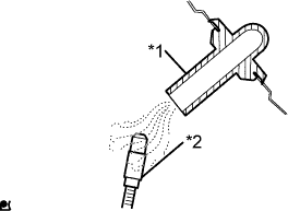
Text in illustration *1 Drain hose *2 Halogen leak detector Bring the halogen leak detector close to the drain hose before performing the test.
Tech Tips
-
After the blower motor has stopped, leave the cooling unit for at least 15 minutes.
-
Place the halogen leak detector sensor under the drain hose.
-
When bringing the halogen leak detector close to the drain hose, make sure that the halogen leak detector does not react to other volatile gases.
If such a reaction is unavoidable, the vehicle must be lifted up.
-
-
If no gas leakage is detected from the drain hose, remove the blower motor from the cooling unit. Insert the halogen leak detector sensor into the unit and perform the test.
-
Disconnect the pressure switch connector and leave it for approximately 20 minutes. Bring the halogen leak detector close to the pressure switch and perform the test.
-