AIR CONDITIONING UNIT REASSEMBLY

-
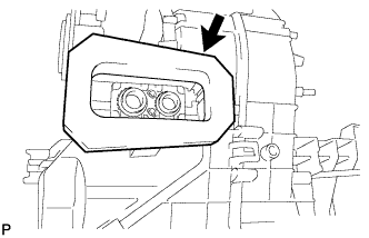
INSTALL NO. 1 COOLER THERMISTOR
-
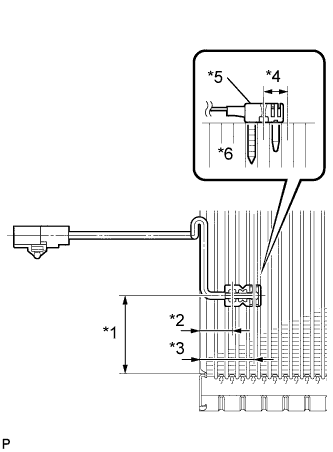
Install front evaporator temperature sensor as shown in the illustration.
Standard Part Length *1 48 to 52 mm (1.890 to 2.047 in.) *2 20.9 mm (0.823 in.) *3 34.3 mm (1.350 in.) Note
-
Be sure to insert the sensor only once because reinserting it will not allow it to be firmly secured.
-
When reusing the evaporator, insert the sensor one row next to the one that was used previously (*4 in the illustration).
-
After inserting the sensor, do not apply excessive force to the wire.
-
Directly insert the sensor until the edge of the plastic case "*5" comes into contact with the evaporator "*6".
-
-
-
INSTALL NO. 1 COOLER EVAPORATOR SUB-ASSEMBLY
Tech Tips
If a new cooler evaporator is installed, add compressor oil to the cooler evaporator as follows.
Capacity Add 40 cc (1.35 fl. oz.) Compressor oil ND-OIL8 or equivalent.
-
Sufficiently apply compressor oil to 2 new O-rings and the fitting surfaces. Install the 2 O-rings onto the cooler evaporator.
Compressor oil ND-OIL 8 or equivalent Note
Keep the O-rings and O-ring fitting surfaces clean from dirt or any foreign objects.
-
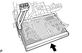
Install the cooler evaporator together with the cooler thermistor as a set.
-
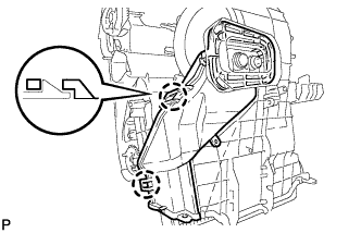
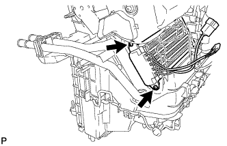
Engage the 2 claws and install the heater case (pipe cover).
-
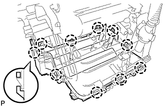
Engage the 10 claws and install the heater case (lower case).
-
Install the new protector.
-
-
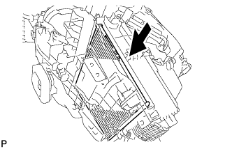
INSTALL CLEAN AIR FILTER
-
Install the clean air filter.
-
-
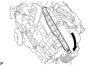
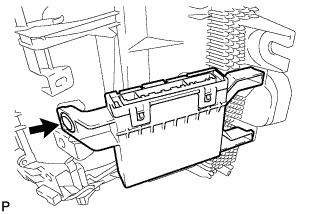
INSTALL AIR FILTER CASE
-
Engage the claw and install the air filter case.
-
-
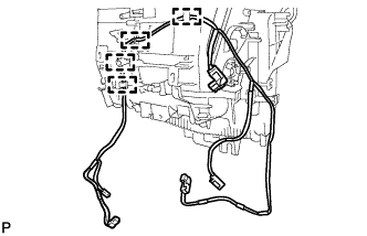
INSTALL AIR CONDITIONING HARNESS ASSEMBLY (for Automatic Air Conditioning System)
-
Engage the 4 claws and install the air conditioning harness.
-
-
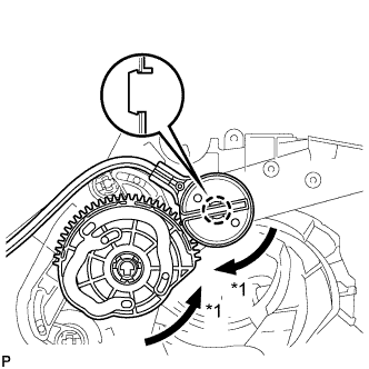
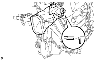
INSTALL MODE DAMPER SERVO SUB-ASSEMBLY (for Automatic Air Conditioning System)
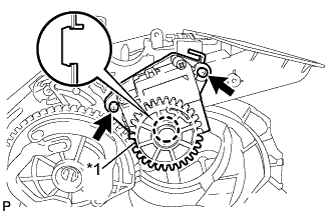
Text in Illustration *1 Reference position
-
Align the reference position and the claw, and then install the mode damper servo.
-
-
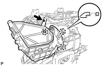
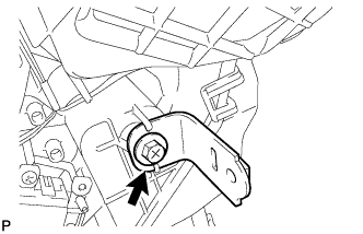
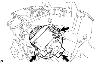
INSTALL HEATER ACCESSORY ASSEMBLY
-
Engage the 3 claws and install the heater accessory.
-
Tighten the screw.
-
-
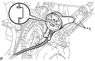
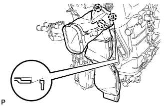
INSTALL DAMPER SERVO SUB-ASSEMBLY (for Automatic Air Conditioning System)
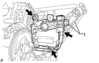
Text in Illustration *1 Reference position
-
Align the reference position and the claw, and then install the damper servo.
-
-
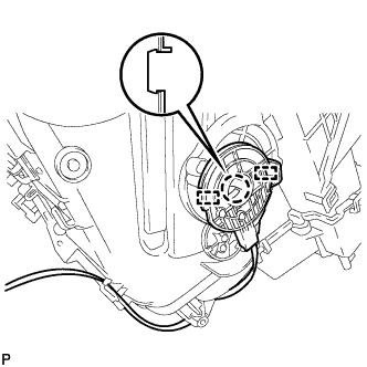
INSTALL AIR MIX DAMPER SERVO SUB-ASSEMBLY (for Automatic Air Conditioning System)
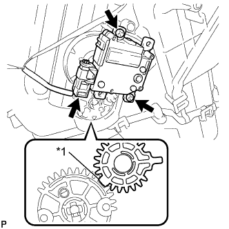
Text in Illustration *1 Reference position
-
Align the reference position and the claw, and then install the air mix damper servo.
-
-
INSTALL NO. 2 HEATER CONTROL CABLE SUB-ASSEMBLY (for Manual Air Conditioning System)
Text in Illustration *1 FACE position
-
Align the heater control cable gear and unit gear in the FACE position.
-
Engage the claw and install the heater control cable.
-
-
INSTALL AIR INLET DAMPER CONTROL CABLE SUB-ASSEMBLY (for Manual Air Conditioning System)
Text in Illustration *1 Reference position
-
Align the reference position and the claw, and then install the air inlet damper cable.
-
-
INSTALL AIR MIX DAMPER CONTROL CABLE SUB-ASSEMBLY (for Manual Air Conditioning System)
-
Engage the claw, 2 guides and install the air mix damper control cable onto the air conditioner unit.
-
Engage the claw and install the air mix damper control cable.
-
-
INSTALL NO. 1 INSTRUMENT PANEL MOUNTING BRACKET
-
Install the instrument panel mounting bracket with the screw.
-
-
INSTALL AIR CONDITIONING AMPLIFIER ASSEMBLY
-
Install the air conditioning amplifier with the clip.
-
-
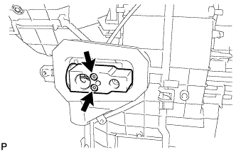
INSTALL COOLER EXPANSION VALVE
-
Using a 4 mm hexagon wrench, install the cooler expansion valve with the 2 hexagon bolts.
- Torque:
- 3.5 N*m { 36 kgf*cm, 31 in.*lbf }
-
-
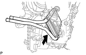
INSTALL HEATER RADIATOR UNIT SUB-ASSEMBLY
-
Install the heater radiator unit.
-
-
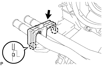
INSTALL NO. 1 COOLER COVER
-
Engage the 2 claws and install the cooler cover.
-
-
INSTALL QUICK HEATER ASSEMBLY (for Cold Area Specification Vehicles)
-
Install the quick heater with the 2 screws.
-
-
INSTALL BLOWER W/FAN MOTOR SUB-ASSEMBLY
-
Install the blower w/fan motor with the 3 screws.
-
-
INSTALL NO. 2 AIR DUCT SUB-ASSEMBLY (except Cold Area Specification Vehicles)
-
Engage the 3 claws and install the air duct.
-
-
INSTALL NO. 1 AIR DUCT SUB-ASSEMBLY (except Cold Area Specification Vehicles)
Tech Tips
Use the same procedure as for the No. 2 side.
-
INSTALL NO. 2 AIR DUCT SUB-ASSEMBLY (for Cold Area Specification Vehicles)
-
Engage the 3 claws and install the air duct.
-
-
INSTALL NO. 1 AIR DUCT SUB-ASSEMBLY (for Cold Area Specification Vehicles)
Tech Tips
Use the same procedure as for the No. 2 side.