AIR CONDITIONING UNIT DISASSEMBLY

-
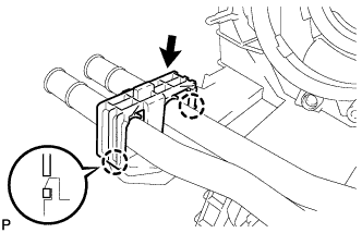
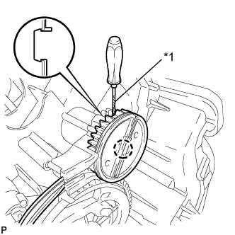
REMOVE NO. 2 AIR DUCT SUB-ASSEMBLY (except Cold Area Specification Vehicles)
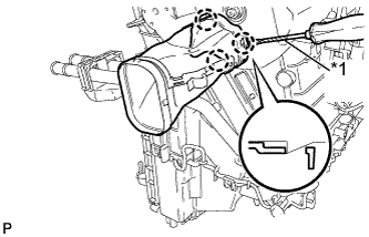
Text in Illustration *1 Protective tape
-
Using a screwdriver with its tip wrapped in protective tape, disengage the 3 claws and remove the air duct.
-
-
REMOVE NO. 1 AIR DUCT SUB-ASSEMBLY (except Cold Area Specification Vehicles)
Tech Tips
Use the same procedure as for the No. 2 side.
-
REMOVE NO. 2 AIR DUCT SUB-ASSEMBLY (for Cold Area Specification Vehicles)
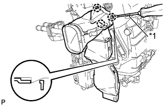
Text in Illustration *1 Protective tape
-
Using a screwdriver with its tip wrapped in protective tape, disengage the 3 claws and remove the air duct.
-
-
REMOVE NO. 1 AIR DUCT SUB-ASSEMBLY (for Cold Area Specification Vehicles)
Tech Tips
Use the same procedure as for the No. 2 side.
-
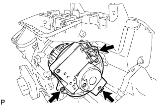
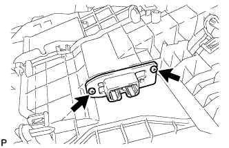
REMOVE BLOWER W/FAN MOTOR SUB-ASSEMBLY
-
Remove the 3 screws.
-
-
REMOVE QUICK HEATER ASSEMBLY (for Cold Area Specification Vehicles)
-
Remove the 2 screws and quick heater.
-
-
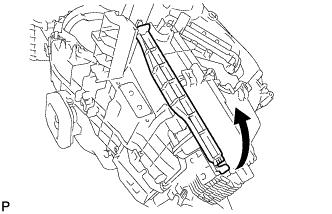
REMOVE NO. 1 COOLER COVER
-
Disengage the 2 claws and remove the cooler cover.
-
-
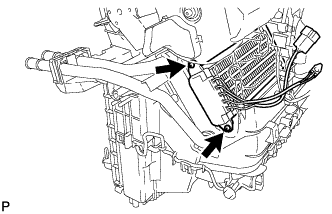
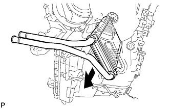
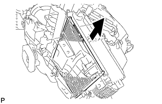
REMOVE HEATER RADIATOR UNIT SUB-ASSEMBLY
-
Remove the heater radiator unit.
-
-
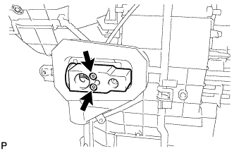
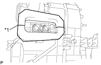
REMOVE COOLER EXPANSION VALVE
-
Using a 4 mm hexagon wrench, remove the 2 hexagon bolts and detach the cooler expansion valve.
-
Remove the 2 O-rings from the cooler evaporator.
-
-
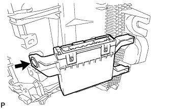
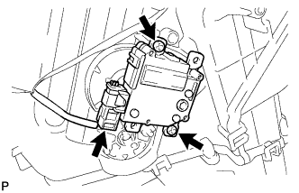
REMOVE AIR CONDITIONING AMPLIFIER ASSEMBLY
-
Remove the clip and air conditioning amplifier.
-
-
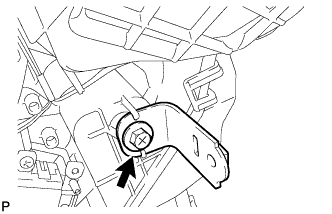
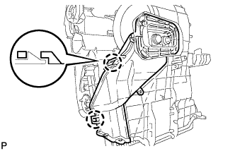
REMOVE NO. 1 INSTRUMENT PANEL MOUNTING BRACKET
-
Remove the screw and instrument panel mounting bracket.
-
-
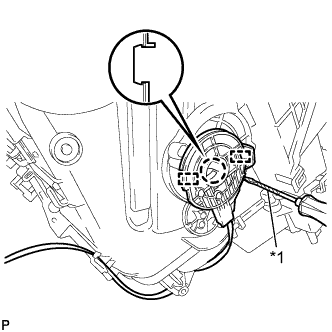
REMOVE AIR MIX DAMPER SERVO SUB-ASSEMBLY (for Automatic Air Conditioning System)
-
Disconnect the connector.
-
Remove the 2 screws and air mix damper servo.
-
-
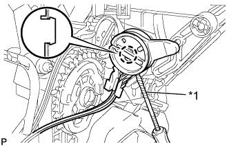
REMOVE DAMPER SERVO SUB-ASSEMBLY (for Automatic Air Conditioning System)
-
Disconnect the connector.
-
Remove the 2 screws and damper servo.
-
-
REMOVE HEATER ACCESSORY ASSEMBLY
-
Remove the screw.
-
Disengage the 3 claws and remove the heater accessory.
-
-
REMOVE MODE DAMPER SERVO SUB-ASSEMBLY (for Automatic Air Conditioning System)
-
Remove the 2 screws.
-
Disengage the claw and remove the mode damper servo.
-
-
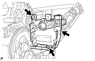
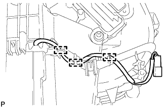
REMOVE AIR CONDITIONING HARNESS ASSEMBLY (for Automatic Air Conditioning System)
-
Disengage the 4 clamps and remove the air conditioning harness.
-
-
REMOVE AIR MIX DAMPER CONTROL CABLE SUB-ASSEMBLY (for Manual Air Conditioning System)
Text in Illustration *1 Protective tape
-
Using a screwdriver with its tip wrapped in protective tape, disengage the claw and the 2 guides and remove the air mix damper control cable.
-
-
REMOVE AIR INLET DAMPER CONTROL CABLE SUB-ASSEMBLY (for Manual Air Conditioning System)
Text in Illustration *1 Protective tape
-
Using a screwdriver with its tip wrapped in protective tape, disengage the claw and remove the air mix damper control cable.
-
-
REMOVE NO. 2 HEATER CONTROL CABLE SUB-ASSEMBLY (for Manual Air Conditioning System)
Text in Illustration *1 Protective tape
-
Using a screwdriver with its tip wrapped in protective tape, disengage the claw and remove the air mix damper control cable.
-
-
REMOVE BLOWER RESISTOR (for Manual Air Conditioning System)
-
Remove the 2 screws and the blower resistor.
-
-
REMOVE AIR FILTER CASE
-
Disengage the claw and air filter case.
-
-
REMOVE CLEAN AIR FILTER
-
Remove the clean air filter.
-
-
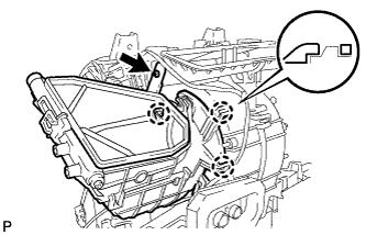
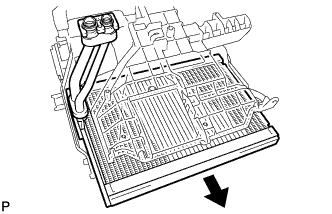
REMOVE NO. 1 COOLER EVAPORATOR SUB-ASSEMBLY
-
Disengage the 3 clamps, and remove the cooler evaporator.
-
Text in Illustration *1 Cut Using a knife, cut off the protector, as shown in the illustration.
-
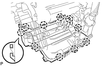
Disengage the 10 claws and remove the heater case (lower case).
-
Disengage the 2 claws and remove the heater case (pipe cover).
-
Remove the cooler evaporator with cooler thermistor.
-
Remove the 2 O-rings from the cooler evaporator.
-
-
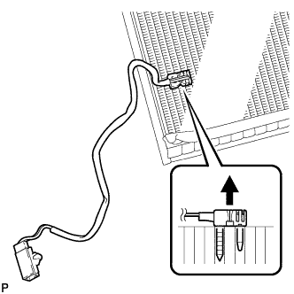
REMOVE NO. 1 COOLER THERMISTOR
-
Remove the front evaporator temperature sensor from the cooler evaporator.
-