COMBUSTION TYPE POWER HEATER SYSTEM Power Heater Fuel Pump Circuit
DESCRIPTION
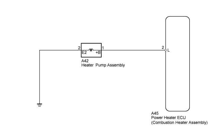
When the power heater switch is turned on, the heater pump assembly receives a drive voltage from the power heater ECU (combustion heater assembly). The heater pump assembly provides the combustion heater with fuel necessary for combustion, allowing the combustion heater to operate.
WIRING DIAGRAM
INSPECTION PROCEDURE
PROCEDURE
-
CHECK HARNESS AND CONNECTOR (COMBUSTION HEATER ASSEMBLY - HEATER PUMP ASSEMBLY)
-
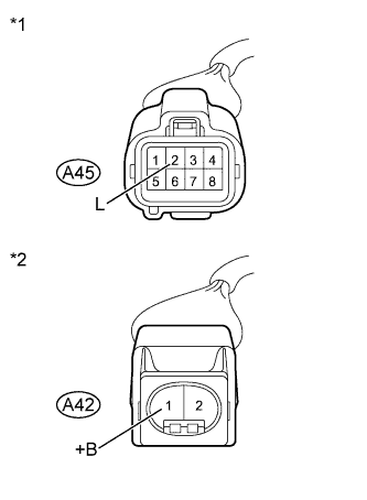
Text in Illustration *1 Front view of wire harness connector
(to Power Heater ECU (Combustion Heater Assembly))
*2 Front view of wire harness connector
(to Heater pump assembly)
Disconnect the A45 power heater ECU (combustion heater assembly) connector.
-
Disconnect the A42 heater pump assembly connector.
-
Measure the resistance according to the value(s) in the table below.
Standard Resistance Tester Connection Condition Specified Condition A45-2 (L) - A42-1 (+B) Always Below 1 Ω A45-2 (L) - Body ground Always 10 kΩ or higher -
Reconnect the heater pump assembly connector.
-
Reconnect the power heater ECU (combustion heater assembly) connector.
NG 
REPAIR OR REPLACE HARNESS OR CONNECTOR
OK 
-
-
CHECK HARNESS AND CONNECTOR (HEATER PUMP ASSEMBLY - BODY GROUND)
-
Disconnect the A42 heater pump assembly connector.
-
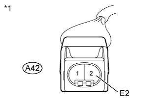
Text in Illustration *1 Front view of wire harness connector
(to Heater pump assembly)
Measure the resistance according to the value(s) in the table below.
Standard Resistance Tester Connection Condition Specified Condition A42-2 (E2) - Body ground Always Below 1 Ω -
Reconnect the heater pump assembly connector.
NG
REPAIR OR REPLACE HARNESS OR CONNECTOR
OK
-
-
INSPECT HEATER PUMP ASSEMBLY
-
Disconnect the A42 heater pump assembly connector.
-
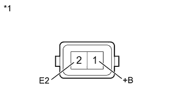
Text in Illustration *1 Component without harness connected
(Heater pump assembly)
Measure the resistance according to the value(s) in the table below.
Standard Resistance Tester Connection Condition Specified Condition 1 (+B) - 2 (E2) Always 9 to 12 Ω -
Inspect heater pump assembly operation.
-
Connect the positive (+) lead from the battery to terminal 1 and the negative (-) lead to terminal 2, and check the pressure of the hose by hand.
CAUTION:
-
This inspection must be done quickly (within 10 seconds) to prevent damage to the heater pump assembly.
-
Always switch the voltage on and off on the battery side, not the heater pump assembly side.
-
Keep the heater pump assembly as far away from the battery as possible.
OK Pressure is applied to the hose. -
-
-
Reconnect the heater pump assembly connector.
NG
REPLACE HEATER PUMP ASSEMBLY Click here
OK 
PROCEED TO NEXT SUSPECTED AREA SHOWN IN PROBLEM SYMPTOMS TABLE Click here
-