COMBUSTION TYPE POWER HEATER SYSTEM Power Heater Alternator Circuit
DESCRIPTION
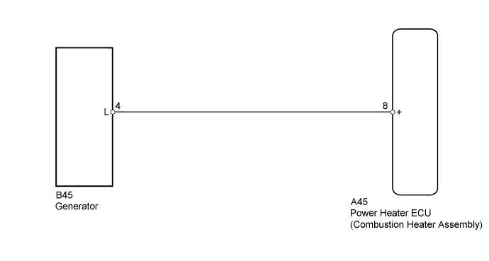
The power heater ECU receives engine operation signals from the L terminal of the generator. If this circuit is open, the power heater ECU will determine that engine operation signals indicate ON. If this circuit is shorted, the power heater ECU will determine that engine operation signals indicate OFF and the power heater will not operate.
WIRING DIAGRAM
INSPECTION PROCEDURE
PROCEDURE
-
INSPECT GENERATOR
-
Inspect the generator.
Item See page On-Vehicle Inspection Inspection
NG 
REPLACE GENERATOR Click here
OK 
-
-
CHECK HARNESS AND CONNECTOR (POWER HEATER ECU (COMBUSTION HEATER ASSEMBLY) - GENERATOR)
-
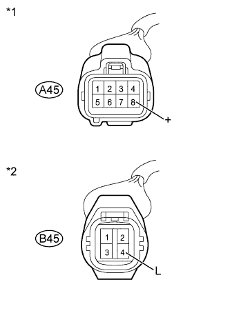
Text in Illustration *1 Front view of wire harness connector
(to Power Heater ECU (Combustion Heater Assembly))
*2 Front view of wire harness connector
(to Generator)
Disconnect the A45 power heater ECU (combustion heater assembly) connector.
-
Disconnect the B45 generator connector.
-
Measure the resistance according to the value(s) in the table below.
Standard Resistance Tester Connection Condition Specified Condition A45-8 (+) - B45-4 (L) Always Below 1 Ω A45-8 (+) - Body ground Always 10 kΩ or higher -
Reconnect the generator connector.
-
Reconnect the power heater ECU (combustion heater assembly) connector.
NG
REPAIR OR REPLACE HARNESS OR CONNECTOR
OK
-
-
CHECK HARNESS AND CONNECTOR (POWER HEATER ECU (COMBUSTION HEATER ASSEMBLY) - BATTERY)
-
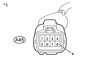
Text in Illustration *1 Front view of wire harness connector
(to Power Heater ECU (Combustion Heater Assembly))
Disconnect the A45 power heater ECU (combustion heater assembly) connector.
-
Measure the voltage according to the value(s) in the table below.
Standard Voltage Tester Connection Condition Specified Condition A45-8 (+) - Body ground Engine idling
(Generator: Operating)
11 to 14 V
NG
REPAIR OR REPLACE HARNESS OR CONNECTOR
OK 
PROCEED TO NEXT SUSPECTED AREA SHOWN IN PROBLEM SYMPTOMS TABLE Click here
-