AIR CONDITIONING SYSTEM (for Manual Air Conditioning System) Blower Motor Circuit
DESCRIPTION
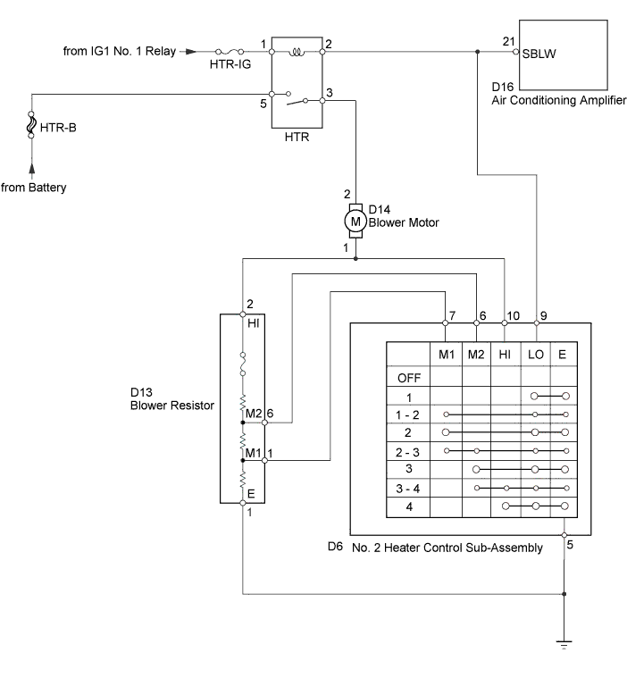
When the No. 2 heater control (blower switch) is set to position 1 or higher, the contact of the HTR relay is closed, current flows to the blower motor, and the blower motor operates. The blower motor speed can be changed by exchanging the ground and the blower resistor circuit with the No. 2 heater control (blower switch).
WIRING DIAGRAM
INSPECTION PROCEDURE
Note
Inspect the fuses for circuits related to this system before performing the following inspection procedures.
PROCEDURE
-
INSPECT HTR RELAY
-
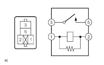
Remove the HTR relay.
-
Measure the resistance according to the value(s) in the table below.
Standard Resistance Tester Connection Condition Specified Condition 3 - 5 Voltage is not applied between terminals 1 and 2 10 kΩ or higher 3 - 5 Apply the battery voltage between terminals 1 and 2 Below 1 Ω -
Reinstall the HTR relay.
NG 
REPLACE HTR RELAY Click here
OK 
-
-
INSPECT BLOWER MOTOR
-
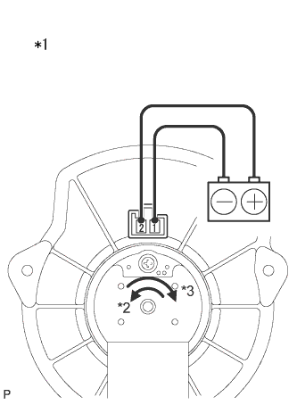
Text in Illustration *1 Component without harness connected
(Blower Motor)
*2 for LHD *3 for RHD Remove the blower motor Click here.
-
Apply battery voltage to the terminals and check that the blower motor operates.
OK Measurement Condition Specified Condition Positive battery - 2
Negative battery - 1
The blower motor operates smoothly. -
Reinstall the blower motor.
NG
REPLACE BLOWER MOTOR Click here
OK
-
-
CHECK HARNESS AND CONNECTOR (HTR FUSE - HTR RELAY)
-
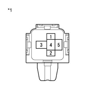
Text in Illustration *1 Front view of wire harness connector
(to HTR Relay)
Remove the HTR Relay.
-
Measure the voltage according to the value(s) in the table below.
Standard Voltage Tester Connection Switch Condition Specified Condition 1 - Body ground Ignition switch ON 11 to 14 V 5 - Body ground Always 11 to 14 V -
Reinstall the HTR Relay.
NG
REPAIR OR REPLACE HARNESS OR CONNECTOR
OK
-
-
CHECK HARNESS AND CONNECTOR (HTR RELAY - NO. 2 HEATER CONTROL SUB-ASSEMBLY)
-
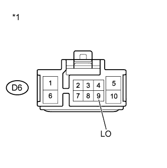
Text in Illustration *1 Front view of wire harness connector
(to No. 2 Heater Control Sub-Assembly (Blower Switch))
Disconnect the D6 No. 2 heater control sub-assembly (blower switch) connector.
-
Measure the voltage according to the value(s) in the table below.
Standard Voltage Tester Connection Switch Condition Specified Condition D6-9 (LO) - Body ground Ignition switch ON 11 to 14 V -
Reconnect the No. 2 heater control sub-assembly (blower switch) connector.
NG
REPAIR OR REPLACE HARNESS OR CONNECTOR
OK
-
-
CHECK HARNESS AND CONNECTOR (HTR RELAY - BLOWER MOTOR)
-
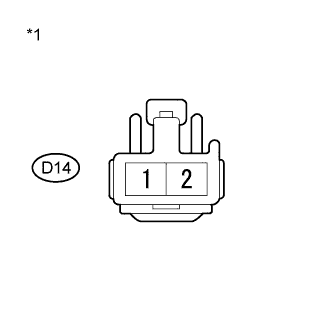
Text in Illustration *1 Front view of wire harness connector
(to Blower Motor)
Disconnect the D14 blower motor connector.
-
Measure the voltage according to the value(s) in the table below.
Standard Voltage Tester Connection Switch Condition Specified Condition D14-2 - Body ground Ignition switch ON
Blower switch on
11 to 14 V -
Reconnect the blower motor connector.
NG
REPAIR OR REPLACE HARNESS OR CONNECTOR
OK
-
-
CHECK HARNESS AND CONNECTOR (BLOWER RESISTOR - BLOWER MOTOR)
-
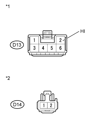
Text in Illustration *1 Front view of wire harness connector
(to Blower Resistor)
*2 Front view of wire harness connector
(to Blower Motor)
Disconnect the D13 blower resistor connector.
-
Disconnect the D14 blower motor connector.
-
Measure the resistance according to the value(s) in the table below.
Standard Resistance Tester Connection Condition Specified Condition D13-2(HI) - D14-1 Always Below 1 Ω -
Reconnect the blower resistor connector.
-
Reconnect the blower motor connector.
NG
REPAIR OR REPLACE HARNESS OR CONNECTOR
OK
-
-
INSPECT BLOWER RESISTOR
-
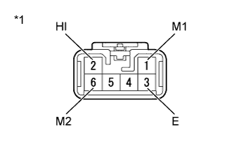
Text in Illustration *1 Component without harness connected
(Blower Resistor)
Remove the blower resistor Click here.
-
Measure the resistance according to the value(s) in the table below.
Standard Resistance Tester Connection Condition Specified Condition 3 (E) - 2 (HI) Always 3.01 to 3.47 Ω 6 (M2) - 2 (HI) Always 0.44 to 0.50 Ω 1 (M1) - 2 (HI) Always 1.53 to 1.75 Ω -
Reinstall the blower resistor.
NG
REPLACE BLOWER RESISTOR Click here
OK
-
-
INSPECT NO. 2 HEATER CONTROL SUB-ASSEMBLY (BLOWER SWITCH)
-
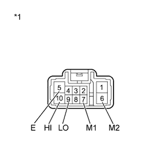
Text in Illustration *1 Component without harness connected
(No. 2 Heater Control Sub-Assembly (Blower Switch))
Remove the No. 2 heater control sub-assembly (blower switch) Click here.
-
Measure the resistance according to the value(s) in the table below.
Standard Resistance Tester Connection Switch Condition Specified Condition ALL - 5 (E) 0 10 kΩ or higher 5 (E) - 9 (LO) 1 Below 1 Ω 5 (E) - 7 (M1) - 9 (LO) 1 - 2 Below 1 Ω 5 (E) - 7 (M1) - 9 (LO) 2 Below 1 Ω 5 (E) - 6 (M2) - 7 (M1) - 9 (LO) 2 -3 Below 1 Ω 5 (E) - 6 (M2) - 9 (LO) 3 Below 1 Ω 5 (E) - 6 (M2) - 9 (LO) - 10 (HI) 3 - 4 Below 1 Ω 5 (E) - 9 (LO) - 10 (HI) 4 Below 1 Ω -
Reinstall the No. 2 heater control sub-assembly (blower switch).
NG
REPLACE NO. 2 HEATER CONTROL SUB-ASSEMBLY Click here
OK
-
-
CHECK HARNESS AND CONNECTOR (NO. 2 HEATER CONTROL SUB-ASSEMBLY - BLOWER RESISTOR)
-
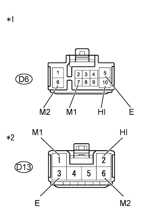
Text in Illustration *1 Front view of wire harness connector
(to No. 2 Heater Control Sub-Assembly (blower switch))
*2 Front view of wire harness connector
(to Blower Resistor)
Disconnect the D6 No. 2 heater control sub-assembly (blower switch) connector.
-
Disconnect the D13 blower resistor connector.
-
Measure the resistance according to the value(s) in the table below.
Standard Resistance Tester Connection Condition Specified Condition D6-5 (E) - D13-3 (E) Always Below 1 Ω D6-6 (M2) - D13-6 (M2) Always Below 1 Ω D6-7 (M1) - D13-1 (M1) Always Below 1 Ω D6-10 (HI) - D13-2 (HI) Always Below 1 Ω -
Reconnect the No. 2 heater control sub-assembly (blower switch) connector.
-
Reconnect the blower resistor connector.
NG
REPAIR OR REPLACE HARNESS OR CONNECTOR
OK 
REPAIR OR REPLACE HARNESS OR CONNECTOR (BLOWER RESISTOR - BODY GROUND)
-