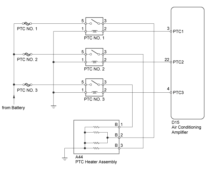
AIR CONDITIONING SYSTEM (for Automatic Air Conditioning System) PTC Heater Circuit
DESCRIPTION
PTC heater relays are closed in accordance with signals from the air conditioning amplifier assembly and power is supplied to the PTC heater assembly installed on the radiator heater unit.
WIRING DIAGRAM
INSPECTION PROCEDURE
Note
Inspect the fuses for circuits related to this system before performing the following inspection procedures.
PROCEDURE
-
INSPECT PTC HEATER RELAY (PTC NO. 1, PTC NO. 2, PTC NO. 3)
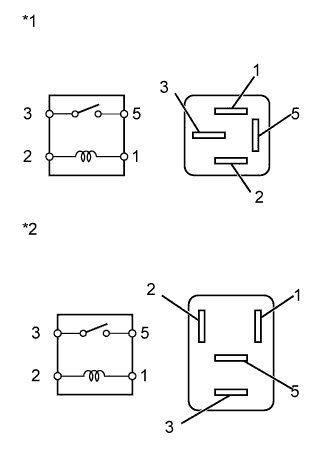
Text in Illustration *1 No. 1 PTC Heater Relay (PTC NO. 1)*3 *2 No. 1 PTC Heater Relay (PTC NO. 1)*4
No. 2 and No. 3 Heater Relay (PTC NO. 2, PTC NO. 3)
-
Remove the PTC heater relays from the No. 2 engine room relay block.
-
Measure the resistance according to the value(s) in the table below.
Standard Resistance Tester Connection Condition Specified Condition 3 - 5 Voltage is not applied between terminals 1 and 2 10 kΩ or higher 3 - 5 Apply the battery voltage between terminals 1 and 2 Below 1 Ω -
Reinstall the PTC heater relays.
*3: for 1ND-TV
*4: for 1KR-FE
NG 
REPLACE PTC HEATER RELAY
OK 
-
-
CHECK HARNESS AND CONNECTOR (FUSE - PTC HEATER RELAY)
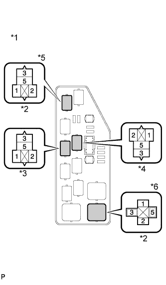
Text in Illustration *1 Component without relay installed
(No. 2 Engine Room Relay Block)
*2 PTC NO. 1 Relay *3 PTC NO. 2 Relay *4 PTC NO. 3 Relay *5 for 1KR-FE *6 for 1ND-TV
-
Remove the PTC heater relays from the No. 2 engine room relay block.
-
Measure the voltage according to the value(s) in the table below.
Standard Voltage Tester Connection Condition Specified Condition PTC NO. 1-5 - Body ground Always 11 to 14 V PTC NO. 2-5 - Body ground Always 11 to 14 V PTC NO. 3-5 - Body ground Always 11 to 14 V -
Reinstall the PTC heater relays.
NG
REPAIR OR REPLACE HARNESS OR CONNECTOR
OK
-
-
CHECK HARNESS AND CONNECTOR (PTC HEATER RELAY - BODY GROUND)
-
Text in Illustration *1 Component without relay installed
(No. 2 Engine Room Relay Block)
*2 PTC NO. 1 Relay *3 PTC NO. 2 Relay *4 PTC NO. 3 Relay *5 for 1KR-FE *6 for 1ND-TV Remove the PTC heater relays from the No. 2 engine room relay block.
-
Measure the resistance according to the value(s) in the table below.
Standard Resistance Tester Connection Condition Specified Condition PTC NO. 1-1 - Body ground Always Below 1 Ω PTC NO. 2-1 - Body ground Always Below 1 Ω PTC NO. 3-1 - Body ground Always Below 1 Ω -
Reinstall the PTC heater relays.
NG
REPAIR OR REPLACE HARNESS OR CONNECTOR
OK
-
-
PERFORM ACTIVE TEST USING INTELLIGENT TESTER (HEATER ACTIVE LEVEL)
-
Text in Illustration *1 Component without relay installed
(No. 2 Engine Room Relay Block)
*2 PTC NO. 1 Relay *3 PTC NO. 2 Relay *4 PTC NO. 3 Relay *5 for 1KR-FE *6 for 1ND-TV Remove the PTC heater relays from the No. 2 engine room relay block.
-
Connect the intelligent tester to the DLC3.
-
Turn the ignition switch to ON.
-
Turn the intelligent tester on.
-
Enter the following menus: Body / Air Conditioner / Active Test / Heater Active Level.
-
Measure the voltage when changing the control range with the intelligent tester, according to the value(s) in the table below.
Standard Voltage Tester Connection Condition Specified Condition PTC NO. 1-2 - Body ground Heater Active Level 0 Below 1 V Heater Active Level 1 11 to 14 V Heater Active Level 2 11 to 14 V Heater Active Level 3 11 to 14 V PTC NO. 2-2 - Body ground Heater Active Level 0 Below 1 V Heater Active Level 1 Below 1 V Heater Active Level 2 11 to 14 V Heater Active Level 3 11 to 14 V PTC NO. 3-2 - Body ground Heater Active Level 0 Below 1 V Heater Active Level 1 Below 1 V Heater Active Level 2 Below 1 V Heater Active Level 3 11 to 14 V -
Reinstall the PTC heater relays.
NG 
CHECK HARNESS AND CONNECTOR (PTC HEATER RELAY - AIR CONDITIONING AMPLIFIER) Click here
OK
-
-
INSPECT PTC HEATER ASSEMBLY
-
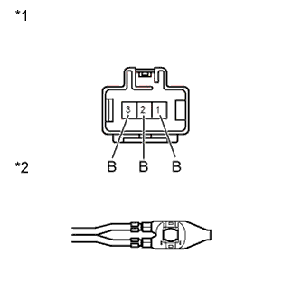
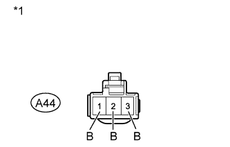
Text in Illustration *1 Component without harness connected
(PTC Heater Assembly)
*2 Component without harness connected
(Ground Terminal (for PTC Heater Assembly))
Disconnect the A44 PTC heater assembly connector.
-
Measure the resistance according to the value(s) in the table below.
Standard Resistance Tester Connection Condition Specified Condition 1 - Ground terminal Always Below 1 Ω 2 - Ground terminal Always Below 1 Ω 3 - Ground terminal Always Below 1 Ω -
Reconnect the PTC heater assembly connector.
NG
REPLACE PTC HEATER ASSEMBLY Click here
OK
-
-
PERFORM ACTIVE TEST USING INTELLIGENT TESTER (HEATER ACTIVE LEVEL)
-
Text in Illustration *1 Front view of wire harness connector
(to PTC Heater Assembly)
Disconnect the A44 PTC heater assembly connector.
-
Connect the intelligent tester to the DLC3.
-
Turn the ignition switch to ON.
-
Turn the intelligent tester on.
-
Enter the following menus: Body / Air Conditioner / Active Test / Heater Active Level.
-
Measure the voltage when changing the control range with an intelligent tester, according to the value(s) in the table below.
Standard Voltage Tester Connection Condition Specified Condition A44-1 (B) - Body ground Heater Active Level 0 Below 1 V Heater Active Level 1 Below 1 V Heater Active Level 2 Below 1 V Heater Active Level 3 11 to 14V A44-2 (B) - Body ground Heater Active Level 0 Below 1 V Heater Active Level 1 11 to 14V Heater Active Level 2 11 to 14V Heater Active Level 3 11 to 14V A44-3 (B) - Body ground Heater Active Level 0 Below 1 V Heater Active Level 1 Below 1 V Heater Active Level 2 11 to 14V Heater Active Level 3 11 to 14V -
Reconnect the PTC heater assembly connector.
NG
REPAIR OR REPLACE HARNESS OR CONNECTOR (PTC HEATER RELAY - PTC HEATER ASSEMBLY)
OK 
PROCEED TO NEXT SUSPECTED AREA SHOWN IN PROBLEM SYMPTOMS TABLE Click here
-
-
CHECK HARNESS AND CONNECTOR (PTC HEATER RELAY - AIR CONDITIONING AMPLIFIER)
-
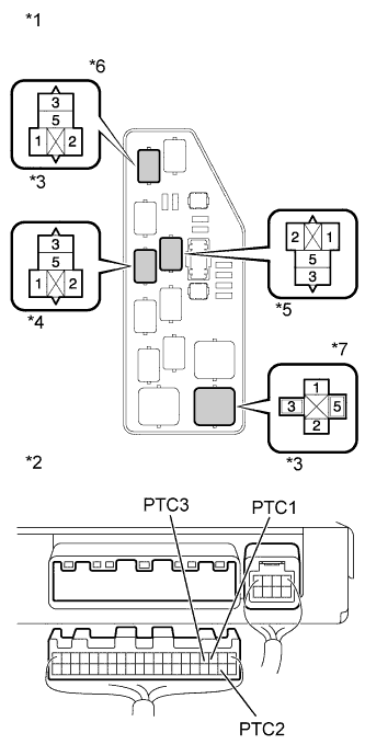
Text in Illustration *1 Component without relay installed
(No. 2 Engine Room Relay Block)
*2 Front view of wire harness connector
(to Air Conditioning Amplifier)
*3 PTC NO. 1 Relay *4 PTC NO. 2 Relay *5 PTC NO. 3 Relay *6 for 1KR-FE *7 for 1ND-TV Remove the PTC heater relays from the No. 2 engine room relay block.
-
Disconnect the D17 air conditioning amplifier connector.
-
Measure the resistance according to the value(s) in the table below.
Standard Resistance Tester Connection Condition Specified Condition PTC NO. 1-2 - D17-9 (PTC1) Always Below 1 Ω PTC NO. 2-2 - D17-10 (PTC2) Always Below 1 Ω PTC NO. 3-2 - D17-12 (PTC3) Always Below 1 Ω -
Reinstall the PTC heater relays.
-
Reconnect the air conditioning amplifier connector.
NG
REPAIR OR REPLACE HARNESS OR CONNECTOR
OK
REPLACE AIR CONDITIONING AMPLIFIER Click here
-