AIR CONDITIONING SYSTEM (for Automatic Air Conditioning System) Blower Motor Circuit
DESCRIPTION
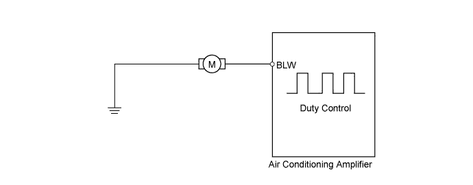
The blower motor is operated by signals from the air conditioning amplifier. Blower motor speed signals are transmitted in accordance with changes in the duty ratio.
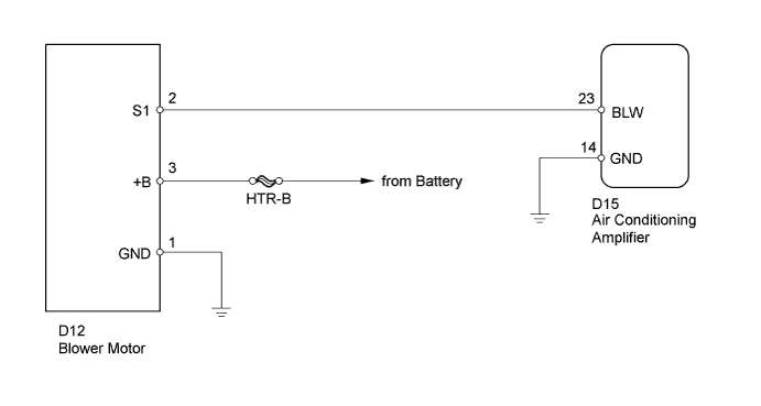
WIRING DIAGRAM
INSPECTION PROCEDURE
Note
Inspect the fuses for circuits related to this system before performing the following inspection procedure.
PROCEDURE
-
PERFORM ACTIVE TEST USING INTELLIGENT TESTER (BLOWER MOTOR)
-
Connect the intelligent tester to the DLC3.
-
Turn the ignition switch to ON.
-
Turn the intelligent tester on.
-
Enter the following menus: Body / Air Conditioner / Active Test / Blower Motor.
-
According to the display on the intelligent tester, check blower motor operation while performing the Active Test.
Air Conditioner Tester Display Test Part Condition Range Diagnostic Note Blower Motor Blower motor Min.: 0, Max.: 31 - Result Result Proceed to OK A NG (blower motor does not operate) B NG (blower motor operates but does not change speed) C
B 
CHECK HARNESS AND CONNECTOR (BLOWER MOTOR - BODY GROUND) Click here
C
CHECK HARNESS AND CONNECTOR (BLOWER MOTOR - AIR CONDITIONING AMPLIFIER) Click here
A 
PROCEED TO NEXT SUSPECTED AREA SHOWN IN PROBLEM SYMPTOMS TABLE Click here
-
-
CHECK HARNESS AND CONNECTOR (BLOWER MOTOR - BODY GROUND)
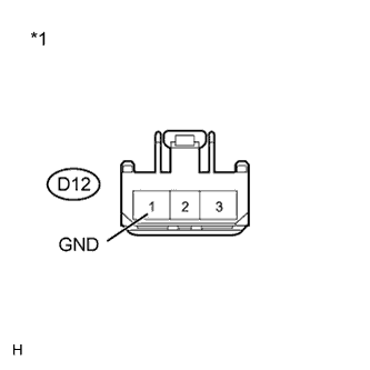
Text in Illustration *1 Front view of wire harness connector
(to Blower Motor)
-
Disconnect the D12 blower motor connector.
-
Measure the resistance according to the value(s) in the table below.
Standard Resistance Tester Connection Condition Specified Condition D12-1 (GND) - Body ground Always Below 1 Ω -
Reconnect the blower motor connector.
NG 
REPAIR OR REPLACE HARNESS OR CONNECTOR
OK 
-
-
CHECK HARNESS AND CONNECTOR (BLOWER MOTOR - BATTERY)
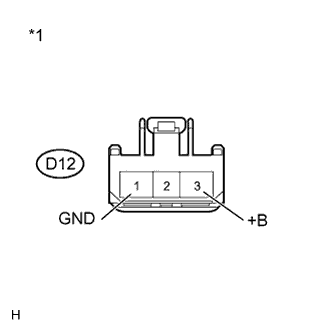
Text in Illustration *1 Front view of wire harness connector
(to Blower Motor)
-
Disconnect the D12 blower motor connector.
-
Turn the ignition switch to ON.
-
Measure the voltage according to the value(s) in the table below.
Standard Voltage Tester Connection Switch Condition Specified Condition D12-3 (+B) - D12-1 (GND) Ignition switch ON 11 to 14 V -
Reconnect the blower motor connector.
NG
REPAIR OR REPLACE HARNESS OR CONNECTOR
OK
-
-
INSPECT BLOWER MOTOR
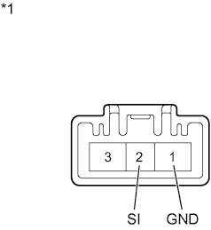
Text in Illustration *1 Component with harness connected
(Blower Motor)
-
Disconnect the D15 air conditioning amplifier connector.
-
Connect the D12 blower motor connector.
-
Turn the ignition switch to ON.
-
Measure the voltage according to the value(s) in the table below.
Standard Voltage Tester Connection Switch Condition Specified Condition D12-2 (SI) - D12-1 (GND) Ignition switch ON 4.5 to 5.5 V -
Reconnect the air conditioning amplifier connector.
NG
REPLACE BLOWER MOTOR Click here
OK
-
-
CHECK HARNESS AND CONNECTOR (BLOWER MOTOR - AIR CONDITIONING AMPLIFIER)
-
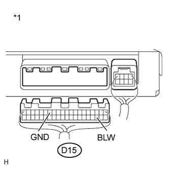
Text in Illustration *1 Rear view of wire harness connector
(to Air Conditioning Amplifier)
Disconnect the D15 air conditioning amplifier connector.
-
Turn the ignition switch to ON.
-
Measure the voltage according to the value(s) in the table below.
Standard Voltage Tester Connection Switch Condition Specified Condition D15-23 (BLW) - D15-14 (GND) Ignition switch ON 4.5 to 5.5 V -
Reconnect the air conditioning amplifier connector.
NG
REPAIR OR REPLACE HARNESS OR CONNECTOR
OK
-
-
INSPECT AIR CONDITIONING AMPLIFIER
-
Remove the air conditioning amplifier with its connectors still connected Click here.
-
Turn the ignition switch to on.
-
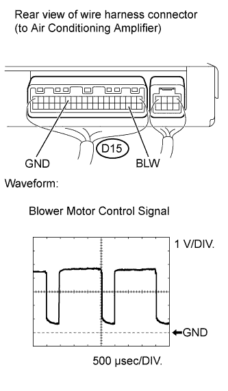
Check the waveform between terminal D15-23 (BLW) of the air conditioning amplifier and the body ground.
OK Waveform is as shown in the illustration. Tech Tips
The waveform varies with the blower level.
Item Content Tester range 1 V / DIV., 500 μs / DIV. Condition Ignition switch ON
Blower switch on (Lo)
Tech Tips
Waveform varies with the blower level.
-
Reinstall the air conditioning amplifier.
NG
REPLACE AIR CONDITIONING AMPLIFIER Click here
OK
REPLACE BLOWER MOTOR Click here
-