AIR CONDITIONING SYSTEM (for Automatic Air Conditioning System), Diagnostic DTC:B1479/79

| DTC Code | DTC Name |
|---|---|
| B1479/79 | Flow Sensor Circuit |
DESCRIPTION
The flow sensor is built into the compressor, and outputs a signal indicating the flow rate of the refrigerant. The air conditioning amplifier converts the received signal to refrigerant flow rate data according to the characteristics of the sensor, which it then sends to the ECM via CAN communication.
| DTC No. | DTC Detection Condition | Trouble Area |
|---|---|---|
| B1479/79 |
|
|
*1: As the flow sensor measures the flow rate of the refrigerant in the air conditioning system, it is necessary to turn the ignition switch to ON in order to check the state of the flow sensor.
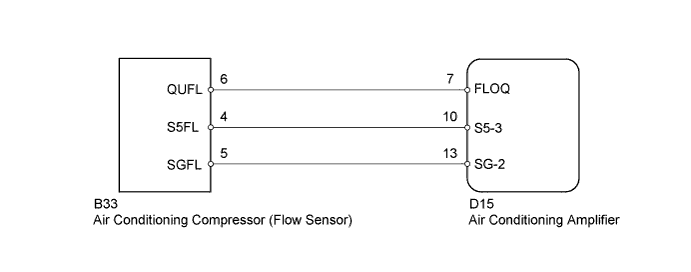
WIRING DIAGRAM
INSPECTION PROCEDURE
Note
-
This DTC is stored when there is no refrigerant in the system, so check refrigerant volume and pressure first when this DTC is output Click here.
PROCEDURE
-
READ VALUE USING INTELLIGENT TESTER (FLOW SENSOR)
-
Connect the intelligent tester to the DLC3.
-
Turn the ignition switch to ON.
-
Turn the intelligent tester on.
-
Enter the following menus: Body / Air Conditioner / Data List.
-
According to the display on the intelligent tester, read the Data List.
Air Conditioning Tester Display Measurement Item/Range Normal Condition Diagnostic Note Flow Sensor Flow sensor/
Min.: 0.0 V, Max.: 5.0 V
Flow sensor voltage displayed Open circuit: 4.7 V or more
Short circuit: 0.3 V or less
Result Result Proceed to 4.7 V or more: Open circuit
(A/C is on)
A 0.3 V or less: Short circuit
(A/C is on)
A Circuit is not open or shorted B
B 
READ VALUE USING INTELLIGENT TESTER (FLOW SENSOR) Click here
A 
-
-
CHECK HARNESS AND CONNECTOR (FLOW SENSOR - AIR CONDITIONING AMPLIFIER)
-
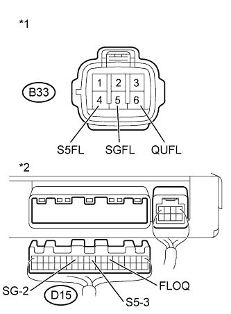
Text in illustration *1 Front view of wire harness connector
(to Air Conditioning Compressor (Flow Sensor))
*2 Rear view of wire harness connector
(to Air Conditioning Amplifier)
Disconnect the B33 air conditioning compressor (flow sensor) connector.
-
Disconnect the D15 air conditioning amplifier connector.
-
Measure the resistance according to the value(s) in the table below.
Standard Resistance Tester Connection Condition Specified Condition B33-6 (QUFL) - D15-7 (FLOQ) Always Below 1 Ω B33-4 (S5FL) - D15-10 (S5-3) Always Below 1 Ω B33-5 (SGFL) - D15-13 (SG-2) Always Below 1 Ω D15-7 (FLOQ) - Body ground Always 10 kΩ or higher D15-10 (S5-3) - Body ground Always 10 kΩ or higher D15-13 (SG-2) - Body ground Always 10 kΩ or higher -
Reconnect the air conditioning compressor (flow sensor) connector.
-
Reconnect the air conditioning amplifier connector.
NG 
REPAIR OR REPLACE HARNESS AND CONNECTOR
OK
-
-
REPLACE AIR CONDITIONING COMPRESSOR (FLOW SENSOR)
-
for 1KR-FE
-
Replace the air conditioning compressor (flow sensor) with a normal one Click here.
-
-
for 1ND-TV
-
Replace the air conditioning compressor (flow sensor) with a normal one Click here.
-
NEXT
-
-
CHECK FOR DTC
-
Clear the DTCs Click here.
-
Check for DTCs Click here.
OK DTC B1479 is not output.
NG
REPLACE AIR CONDITIONING AMPLIFIER Click here
OK 
END (AIR CONDITIONING COMPRESSOR (FLOW SENSOR) IS FAULTY)
-
-
READ VALUE USING INTELLIGENT TESTER (FLOW SENSOR)
-
Connect the intelligent tester to the DLC3.
-
Turn the ignition switch to ON.
-
Turn the intelligent tester on.
-
Enter the following menus: Body / Air Conditioner / Data List.
-
According to the display on the intelligent tester, read the Data List.
Air Conditioner Tester Display Measurement Item/Range Normal Condition Diagnostic Note Flow sensor Flow Sensor/
Min.: 0.0 V, Max.: 5.0 V
Flow sensor voltage displayed Open circuit: 4.7 V or more
Short circuit: 0.3 V or less
Result Result Proceed to Sensor is stuck in an intermediate position
-
Engine idling
-
A/C switch off
-
Sensor voltage is 3.76 V or less and does not change for 8.5 minutes or more
A Sensor is stuck at zero position
-
Engine idling
-
A/C switch on
-
Sensor voltage is 3.76 V or more and does not change for 8.5 minutes or more
A Sensor is not stuck (When troubleshooting according to the Problem Symptoms Table) B Sensor is not stuck (When troubleshooting according to the DTC output) C -
B
PROCEED TO NEXT SUSPECTED AREA SHOWN IN PROBLEM SYMPTOMS TABLE
C
CHECK FOR DTC Click here
A
-
-
CHECK REFRIGERANT PRESSURE
-
Install the manifold gauge set.
-
Read the gauge pressure to check that refrigerant has been charged Click here.
OK Refrigerant is charged.
NG
CHARGE REFRIGERANT
OK
-
-
REPLACE AIR CONDITIONING COMPRESSOR (FLOW SENSOR)
-
for 1KR-FE
-
Replace the air conditioning compressor (flow sensor) with a normal one Click here.
Note
In some cases, this DTC is stored when the magnetic clutch is not functioning properly, so inspect the magnet clutch clearance before replacing the air conditioning compressor (flow sensor) Click here.
-
-
for 1ND-TV
-
Replace the air conditioning compressor (flow sensor) with a normal one Click here.
Note
In some cases, this DTC is stored when the magnetic clutch is not functioning properly, so inspect the magnet clutch clearance before replacing the air conditioning compressor (flow sensor) Click here.
-
NEXT
-
-
CHECK FOR DTC
-
Clear the DTCs Click here.
-
Check for DTCs Click here.
OK DTC B1479 is not output.
NG
REPLACE AIR CONDITIONING AMPLIFIER Click here
OK
END (AIR CONDITIONING COMPRESSOR (FLOW SENSOR) IS FAULTY)
-