AIR CONDITIONING SYSTEM (for Automatic Air Conditioning System) SYSTEM DESCRIPTION

-
GENERAL
The air conditioning system has the following controls:
Control Outline Neural Network Control This control is capable of effecting complex control by artificially simulating the information processing method of the nervous system of living organisms in order to establish a complex input or output relationship that is similar to a human brain. Outlet Air Temperature Control In compliance with the temperature set at the temperature control switch, the neural network control calculates the outlet temperature based on the input signals from various sensors. In addition, corrections in accordance with the signals from the evaporative temperature sensor and water temperature sensor are added to control the outlet air temperature. Blower Control Controls the blower motor in accordance with the airflow volume that has been calculated by the neural network control based on the input signals from various sensors. Air Outlet Control Automatically switches the outlets in accordance with the outlet mode ratio that has been calculated by the neural network control based on the input signals from various sensors. Air Inlet Control Automatically controls the air inlet control damper in accordance with the airflow volume that has been calculated by the neural network control. Variable Capacity Compressor Control Through the calculation of the target evaporator temperature based on various sensor signals, the air conditioning amplifier optimally controls the discharge capacity by regulating the opening extent of the cooler compressor solenoid control valve. PTC Heater Control* When the ignition switch is turned ON, and the blower motor is turned on, the air conditioning amplifier turns on the PTC heater assembly if the conditions listed below are met.
-
Engine coolant temperature is below specified temperature.
-
Ambient temperature is below specified temperature.
-
Tentative air mix damper opening angle is above the specified value (MAX HOT).
*: w/ PTC heater
-
-
MODE POSITION AND DAMPER OPERATION
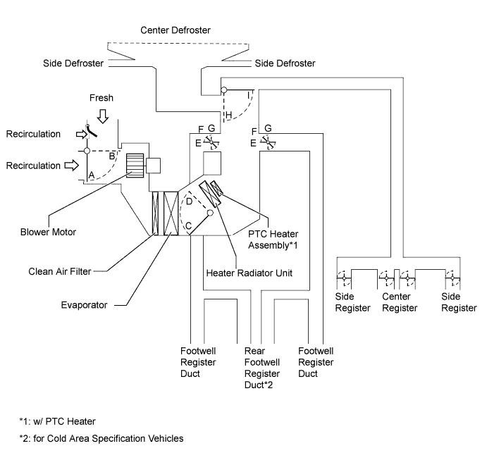
Control Damper Operation Position Damper Position Operation Air Inlet Control Damper FRESH A Brings in fresh air. RECIRC B Recirculates internal air. Air Mix Control Damper MAX COLD - MAX HOT C, D Varies the mixture ratio of the fresh air and the recirculation air in order to regulate the temperature continuously from HOT to COLD. Mode Control Damper DEF

G, I Defrosts the windshield through the center defroster, side defroster, and side register. FOOT / DEF

F, I Defrosts the windshield through the front defroster, side defroster and side register, while air is also blown out from the footwell register duct and rear footwell register duct*. FOOT

E, I Air blows out of the footwell register duct, rear footwell register duct*, and side register. In addition, air blows out slightly from the front defroster and side defroster. BI-LEVEL

F, H Air blows out of the center register, side register, footwell register and rear footwell register duct*. FACE

G, H Air blows out of the center register and side register. *: for Cold area specification vehicles
-
AIR OUTLETS AND AIRFLOW VOLUME
Operation Position FACE FOOT DEFROSTER Center Side Front Rear* A B C D E FACE


BI-LEVEL


FOOT

FOOT/DEF
DEF
The size of the circle ○ indicates the proportion of airflow volume.
*: for Cold area specification vehicles