AIR CONDITIONING SYSTEM (for Manual Air Conditioning System) Generator Signal Circuit
DESCRIPTION
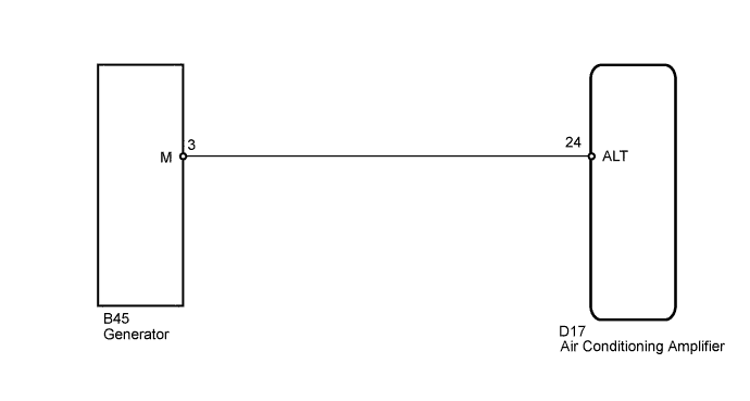
When the engine is started, the generator rotates and a pulsed voltage signal is generated. This signal is used by the air conditioning amplifier. The generated voltage signals sent from the generator are used for controlling the number of the heater elements to be heated.
WIRING DIAGRAM
INSPECTION PROCEDURE
PROCEDURE
-
CHECK HARNESS AND CONNECTOR (AIR CONDITIONING AMPLIFIER - GENERATOR)
-
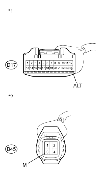
Text in Illustration *1 Front view of wire harness connector
(to Air Conditioning Amplifier)
*2 Front view of wire harness connector
(to generator)
Disconnect the D17 air conditioning amplifier connector.
-
Disconnect the B45 generator connector.
-
Measure the resistance according to the value(s) in the table below.
Standard Resistance Tester Connection Condition Specified Condition D17-24 (ALT) - B45-3 (M) Always Below 1 Ω D17-24 (ALT) - Body ground Always 10 kΩ or higher -
Reconnect the generator connector.
-
Disconnect the air conditioning amplifier connector.
NG 
REPAIR OR REPLACE HARNESS OR CONNECTOR
OK 
-
-
INSPECT GENERATOR
-
Inspect the generator Click here(for 1KR-FE), Click here(1ND-TV).
Result Result Proceed to OK A NG (for 1KR-FE) B NG (for 1ND-TV) C
B
REPLACE GENERATOR (for 1KR-FE) Click here
C
REPLACE GENERATOR (for 1ND-TV) Click here
A 
PROCEED TO NEXT SUSPECTED AREA SHOWN IN PROBLEM SYMPTOMS TABLE Click here
-