AIR CONDITIONING SYSTEM (for Manual Air Conditioning System) Headlight Signal Circuit
DESCRIPTION
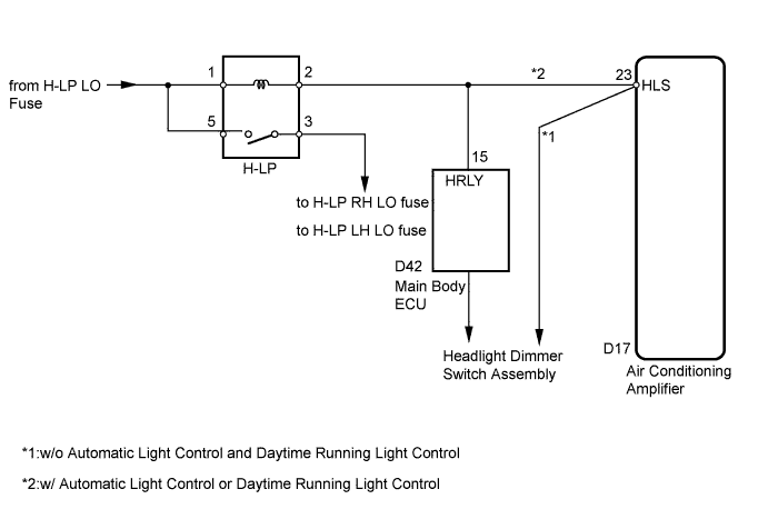
The air conditioning amplifier receives headlight operational signals to determine electrical load conditions. The electrical load condition signals are used for controlling the number of the PTC heater elements to be heated.
WIRING DIAGRAM
INSPECTION PROCEDURE
Note
Inspect the fuses for circuits related to this system before performing the following inspection procedures.
PROCEDURE
-
INSPECT HEADLIGHT ASSEMBLY
-
Check that the headlight comes on when the light control switch is turned to the HEAD position.
OK The headlight comes on.
NG 
GO TO LIGHTING SYSTEM Click here
OK 
-
-
CHECK HARNESS AND CONNECTOR (H-LP RELAY - AIR CONDITIONING AMPLIFIER)
-
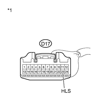
Text in Illustration *1 Front view of wire harness connector
(to Air Conditioning Amplifier )
Disconnect the D17 air conditioning amplifier connector.
-
Measure the voltage according to the value(s) in the table below.
Standard Voltage Tester Connection Switch Condition Specified Condition D17-23 (HLS) - Body ground Light control switch: off 11 to 14 V Light control switch: HEAD Below 1 V -
Reconnect the air conditioning amplifier connector.
NG
REPAIR OR REPLACE HARNESS OR CONNECTOR
OK 
PROCEED TO NEXT SUSPECTED AREA SHOWN IN PROBLEM SYMPTOMS TABLE Click here
-