FRONT SEAT OUTER BELT ASSEMBLY REMOVAL

CAUTION:
Some of these service operations affect the SRS airbag system. Read the precautionary notices concerning the SRS airbag system before servicing Click here.
Tech Tips
The procedure described below is for the RH side. Use the same procedure for both the RH and LH sides, unless otherwise specified.
-
DISCONNECT CABLE FROM NEGATIVE BATTERY TERMINAL
CAUTION:
Wait for at least 90 seconds after disconnecting the cable from the negative (-) battery terminal to disable the SRS system.
-
REMOVE REAR SEAT ASSEMBLY (w/ Rear Seat Assembly)
-
Remove the rear seat assembly (w/ Rear Seat Assembly) Click here.
-
-
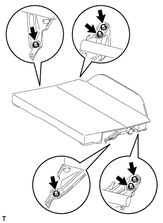
REMOVE REAR SEAT SUB FLOOR BOARD ASSEMBLY (w/o Rear Seat Assembly)
-
Remove the 6 bolts and rear floor board.
-
-
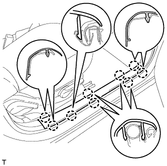
REMOVE FRONT DOOR SCUFF PLATE RH
-
Disengage the 9 claws and remove the front door scuff plate.
-
-
REMOVE FRONT DOOR OPENING TRIM WEATHERSTRIP RH
-
Remove the front door opening trim weatherstrip to the extent that the side No. 1 trim assembly RH can be removed.
-
-
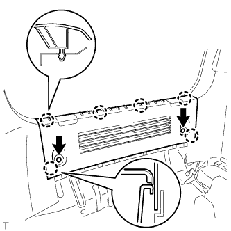
REMOVE REAR DECK TRIM COVER
-
Remove the 2 clips.
-
Disengage the 6 claws and remove the rear deck trim cover.
-
-
REMOVE BACK DOOR WEATHERSTRIP
-
Remove the back door weatherstrip to the extent that the side No. 1 trim assembly RH can be removed.
-
-
REMOVE DECK TRIM SIDE BELT HOLE COVER RH
-
Disengage the 5 claws and remove the deck trim side belt hole cover.
-
-
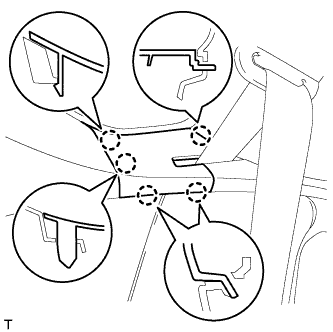
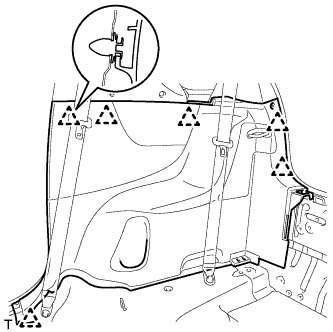
REMOVE NO. 1 SIDE TRIM ASSEMBLY RH
-
Disengage the 6 clips and remove the side No. 1 trim.
-
-
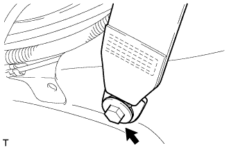
SEPARATE FRONT SEAT OUTER BELT ASSEMBLY
-
Remove the bolt and the front seat outer belt.
-
-
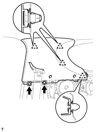
REMOVE CENTER PILLAR UPPER GARNISH
-
Remove the 2 clips.
-
Disengage the 4 clips and remove the center pillar upper garnish.
-
Remove the 3 clip caps from the body side.
-
-
REMOVE FRONT SEAT OUTER BELT ASSEMBLY
-
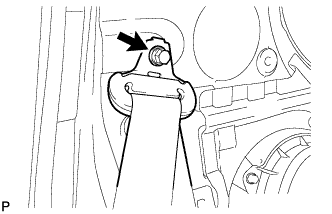
Remove the bolt and the shoulder anchor.
-
Disconnect the pretensioner connector.
-
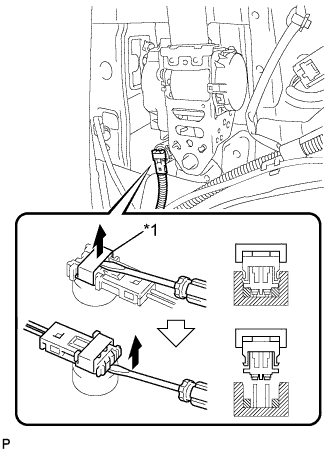
Text in Illustration *1 Locking Button Using a screwdriver, release the locking button.
-
Using a screwdriver, disconnect the pretensioner connector.
-
-
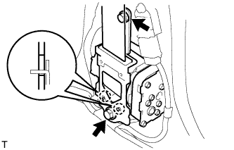
Remove the 2 bolts, the 2 hooks and the retractor.
-