SEAT BELT WARNING SYSTEM Front Passenger Side Seat Belt Warning Light Malfunction
DESCRIPTION
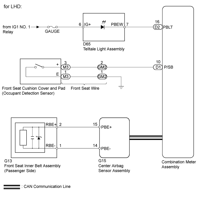
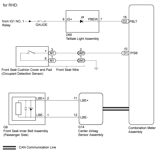
The center airbag sensor assembly detects the state of the front seat inner belt when the front passenger seat is occupied with the ignition switch ON. The center airbag sensor assembly transmits the front passenger seat belt state signal to the combination meter. If the front passenger seat belt is not fastened, the combination meter blinks the front seat belt warning light on the telltale light. If the seat belt is fastened, the warning light goes off.
WIRING DIAGRAM
INSPECTION PROCEDURE
Note
-
Since the seat belt warning system has functions that use CAN communication, first confirm that there is no malfunction in the communication system by inspecting the CAN communication functions in accordance with How to Proceed with Troubleshooting. Then conduct the following troubleshooting procedure.
-
Inspect the fuses for circuits related to this system before performing the following inspection procedure.
PROCEDURE
-
CHECK DTC OUTPUT
-
Check for DTCs.
Result Result Proceed to B1656/38 is not output A B1656/38 is output B
B 
GO TO AIRBAG SYSTEM Click here
A 
-
-
PERFORM ACTIVE TEST USING INTELLIGENT TESTER
-
Connect the intelligent tester to the DLC3.
-
Turn the ignition switch to ON.
-
Turn the tester on.
-
Enter the following menus: Body / Combination Meter / Active Test.
-
According to the display on the tester, perform the Active Test.
Combination Meter Item Test Part Control Range Diagnostic Note Front Passenger Side Seat Belt Front passenger side seat belt warning light ON/OFF - OK Passenger seat belt warning light condition can be switched by Active Test.
NG 
CHECK HARNESS AND CONNECTOR (COMBINATION METER ASSEMBLY - TELLTALE LIGHT ASSEMBLY) Click here
OK
-
-
CHECK HARNESS AND CONNECTOR (FRONT SEAT WIRE - COMBINATION METER AND BODY GROUND)
-
Disconnect the GM2*1 or GM1*2 front seat wire connector.
-
*1: for LHD
-
*2: for RHD
-
-
Disconnect the D1 combination meter assembly connector.
-
Measure the resistance according to the value(s) in the table below.
Standard Resistance for LHD Tester Connection Condition Specified Condition GM2-2 - D1-10 (P/SB) Always Below 1 Ω GM2-2 or D1-10 (P/SB) - Body ground Always 10 kΩ or higher GM2-1 - Body ground Always Below 1 Ω for RHD Tester Connection Condition Specified Condition GM1-2 - D1-10 (P/SB) Always Below 1 Ω GM1-2 or D1-10 (P/SB) - Body ground Always 10 kΩ or higher GM1-1 - Body ground Always Below 1 Ω -
Reconnect the front seat wire connector.
-
Reconnect the combination meter assembly connector.
NG
REPAIR OR REPLACE HARNESS OR CONNECTOR
OK
-
-
INSPECT FRONT SEAT WIRE
-
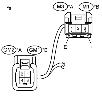
Text in Illustration *A for LHD *B for RHD *a Component without harness connected
(Front Seat Wire)
Disconnect the M3 and GM2*1 or M1 and GM1*2 front seat wire connectors.
-
*1: for LHD
-
*2: for RHD
-
-
Measure the resistance according to the value(s) in the table below.
Standard Resistance for LHD Tester Connection Condition Specified Condition GM2-2 - M3-3 (+) Always Below 1 Ω GM2-2 or M3-3 (+) - Body ground Always 10 kΩ or higher GM2-1 - M3-1 Always Below 1 Ω for RHD Tester Connection Condition Specified Condition GM1-2 - M1-3 (+) Always Below 1 Ω GM1-2 or M1-3 (+) - Body ground Always 10 kΩ or higher GM1-1 - M1-1 Always Below 1 Ω -
Reconnect the front seat wire connectors.
NG
REPLACE FRONT SEAT WIRE Click here
OK
-
-
INSPECT FRONT SEAT CUSHION PAD SUB-ASSEMBLY (OCCUPANT DETECTION SENSOR)
-
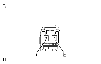
Text in Illustration *a Component without harness connected
(Occupant Detection Sensor)
Disconnect the occupant detection sensor connector.
-
Measure the resistance according to the value(s) in the table below.
Standard Resistance Tester Connection Condition Specified Condition 1 (E) - 3 (+) Passenger seat is occupied Below 100 Ω Passenger seat is not occupied 1 MΩ or higher -
Reconnect the occupant detection sensor connector.
NG
REPLACE FRONT SEAT CUSHION PAD SUB-ASSEMBLY (OCCUPANT DETECTION SENSOR) Click here
OK 
REPLACE COMBINATION METER ASSEMBLY Click here
-
-
CHECK HARNESS AND CONNECTOR (COMBINATION METER ASSEMBLY - TELLTALE LIGHT ASSEMBLY)
-
Disconnect the D2 combination meter assembly connector.
-
Disconnect the D65 telltale light assembly connector.
-
Measure the resistance according to the value(s) in the table below.
Standard Resistance Tester Connection Condition Specified Condition D2-16 (PBLT) - D65-7 (PBEW) Always Below 1 Ω D2-16 (PBLT) or D65-7 (PBEW) - Body ground Always 10 kΩ or higher -
Reconnect the combination meter assembly connector.
-
Reconnect the telltale light assembly connector.
NG
REPAIR OR REPLACE HARNESS OR CONNECTOR
OK
-
-
INSPECT TELLTALE LIGHT ASSEMBLY
-
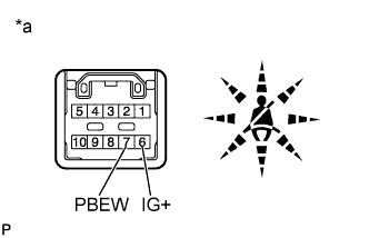
Text in Illustration *a Component without harness connected
(Telltale Light Assembly)
Remove the telltale light assembly.
-
Apply battery voltage to the terminals and check that the front passenger seat belt warning light illuminates.
OK Measurement Condition Specified Condition Positive battery - Terminal 6 (lG+)
Negative battery - Terminal 7 (PBEW)
Front passenger seat belt warning light Illuminates -
Reinstall the telltale light assembly.
NG
REPLACE TELLTALE LIGHT ASSEMBLY Click here
OK
REPLACE COMBINATION METER ASSEMBLY Click here
-