SEAT BELT WARNING SYSTEM Driver Side Seat Belt Warning Light does not Operate
DESCRIPTION
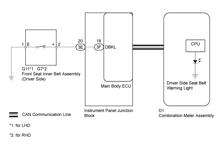
When the ignition switch is ON, the main body ECU communicates the status of the front seat inner belt (driver side) to the combination meter assembly using the CAN communication line. When the seat belt is unfastened, the combination meter assembly flashes the driver side seat belt warning light on the combination meter assembly. When the seat belt is fastened, the combination meter assembly stops flashing the warning light.
WIRING DIAGRAM
INSPECTION PROCEDURE
Note
Since the seat belt warning system has functions that use CAN communication, first confirm that there is no malfunction in the communication system by inspecting the CAN communication functions in accordance with How to Proceed with Troubleshooting. Then conduct the following troubleshooting procedure.
PROCEDURE
-
PERFORM ACTIVE TEST USING INTELLIGENT TESTER (DRIVER SIDE SEAT BELT)
-
Connect the intelligent tester to the DLC3.
-
Turn the ignition switch to ON.
-
Turn the tester on.
-
Enter the following menus: Body / Combination Meter / Active Test.
-
According to the display on the tester, perform the Active Test.
Combination Meter Item Test Part Control Range Diagnostic Note Driver Side Seat Belt Driver side seat belt warning light ON / OFF - OK Driver side seat belt warning light condition can be switched by Active Test.
NG 
REPLACE COMBINATION METER ASSEMBLY Click here
OK 
-
-
READ VALUE USING INTELLIGENT TESTER (D SEAT BUCKLE SW)
-
Connect the intelligent tester to the DLC3.
-
Turn the ignition switch to ON.
-
Turn the tester on.
-
Enter the following menus: Body / Main Body / Data List.
-
According to the display on the tester, read the Data List.
Main Body Tester Display Measurement Item/Range Normal Condition Diagnostic Note D Seat Buckle SW Buckle switch (Driver side)/ ON or OFF ON: Driver side seat belt is fastened
OFF: Driver side seat belt is unfastened
- OK The display is as specified in the normal condition column.
NG 
INSPECT FRONT SEAT INNER BELT ASSEMBLY (DRIVER SIDE) Click here
OK 
USE SIMULATION METHOD TO CHECK Click here
-
-
INSPECT FRONT SEAT INNER BELT ASSEMBLY (DRIVER SIDE)
-
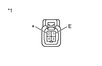
Text in Illustration *1 Component without harness connected
(Front Seat Inner Belt (Driver Side))
Disconnect the G11 or G7 front seat inner belt assembly (driver side) connector.
-
Measure the resistance according to the value(s) in the table below.
Standard Resistance Tester Connection Condition Specified Condition 1 (E) - 2 (+) Tongue plate fastened 10 kΩ or higher Tongue plate unfastened Below 1 Ω -
Reconnect the front seat inner belt assembly (driver side) connector.
NG
REPLACE FRONT SEAT INNER BELT ASSEMBLY (DRIVER SIDE) Click here
OK
-
-
CHECK HARNESS AND CONNECTOR (FRONT SEAT INNER BELT - INSTRUMENT PANEL JUNCTION BLOCK)
-
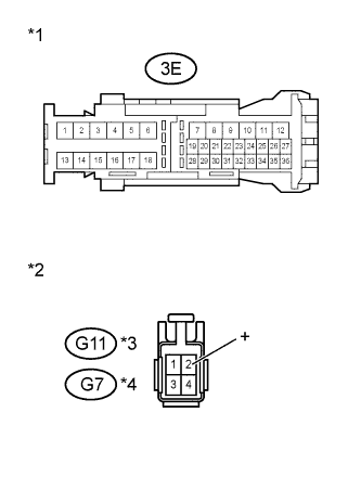
Text in Illustration *1 Front view of wire harness connector
(to Instrument Panel Junction Block)
*2 Front view of wire harness connector
(to Front Seat Inner Belt (Driver Side))
*3 for LHD *4 for RHD Disconnect the G11 or G7 front seat inner belt assembly (driver side) connector.
-
Disconnect the 3E instrument panel junction block connector.
-
Measure the resistance according to the value(s) in the table below.
Standard Resistance for LHD Tester Connection Condition Specified Condition 3E-20 - G11-2 (+) Always Below 1 Ω 3E-20 or G11-2 (+) - Body ground Always 10 kΩ or higher for RHD Tester Connection Condition Specified Condition 3E-20 - G7-2 (+) Always Below 1 Ω 3E-20 or G7-2 (+) - Body ground Always 10 kΩ or higher -
Reconnect the front seat inner belt assembly (driver side) connector.
-
Reconnect the instrument panel junction block connector.
NG
REPAIR OR REPLACE HARNESS OR CONNECTOR
OK
-
-
CHECK HARNESS AND CONNECTOR (FRONT SEAT INNER BELT ASSEMBLY (DRIVER SIDE) - BODY GROUND)
-
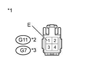
Text in Illustration *1 Front view of wire harness connector
(to Front Seat Inner Belt (Driver Side))
*2 for LHD *3 for RHD Disconnect the G11 or G7 front seat inner belt assembly (driver side) connector.
-
Measure the resistance according to the value(s) in the table below.
Standard Resistance for LHD Tester Connection Condition Specified Condition G11-1 (E) - Body ground Always Below 1 Ω for RHD Tester Connection Condition Specified Condition G7-1 (E) - Body ground Always Below 1 Ω -
Reconnect the front seat inner belt assembly (driver side) connector.
NG
REPAIR OR REPLACE HARNESS OR CONNECTOR
OK
-
-
REPLACE MAIN BODY ECU
-
Temporarily replace the main body ECU with a new or normally functioning one Click here.
NEXT
-
-
READ VALUE USING INTELLIGENT TESTER
-
Connect the intelligent tester to the DLC3.
-
Turn the ignition switch to ON.
-
Turn the tester on.
-
Enter the following menus: Body / Main Body / Data List.
-
According to the display on the tester, read the Data List.
Main Body Tester Display Measurement Item/Range Normal Condition Diagnostic Note D Seat Buckle SW Buckle switch (Driver side)/ ON or OFF ON: Driver side seat belt is fastened
OFF: Driver side seat belt is unfastened
- OK The display is as specified in the normal condition column.
NG
REPLACE INSTRUMENT PANEL JUNCTION BLOCK
OK
END (MAIN BODY ECU IS DEFECTIVE)
-