FRONT AIRBAG SENSOR INSTALLATION

CAUTION:
Some of these service operations affect the SRS airbag system. Read the precautionary notices concerning the SRS airbag system before servicing Click here.
-
INSTALL FRONT AIRBAG SENSOR LH
Note
-
Do not use a front airbag sensor that has been dropped.
-
Do not subject the front airbag sensor to any impact or force.
-
Confirm that the ignition switch is off.
-
Confirm that the cable to the negative battery terminal is disconnected.
CAUTION:
-
Confirm that the negative battery terminal is disconnected before performing the operation. Even an impact to only the airbag sensor will cause the airbag to deploy.
-
Wait at least 90 seconds after disconnecting the cable from the negative (-) battery terminal to disable the SRS system.
-
-
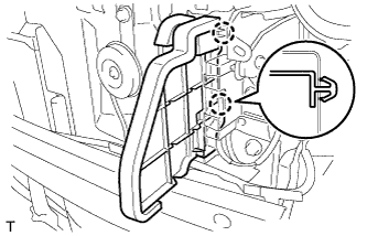
Install the front airbag sensor with the bolt.
- Torque:
- 9.0 N*m { 92 kgf*cm, 80 in.*lbf }
-
Connect the airbag connector.
-
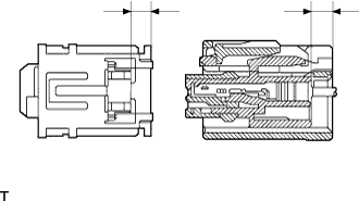
Check that the CPA is in the provisionally locked state.
-
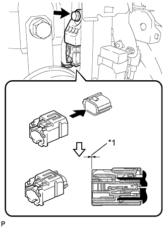
Text in Illustration *1 Conform Push the CPA until it makes a click sound.
Note
-
Engage the connector by pushing it straight.
-
Hold the CPA when engaging the connector.
-
Do not engage the CPA while pressing the CPA upper portion, because otherwise, the half connection prevention mechanism will not function.
-
-
Confirm that the rear side of the housing and the CPA rear surface are tightly fitted together.
-
-
Confirm that there is no looseness by shaking the front airbag sensor.
-
-
INSTALL FRONT AIRBAG SENSOR RH
Note
-
Do not use a front airbag sensor that has been dropped.
-
Do not subject the front airbag sensor to any impact or force.
-
Confirm that the ignition switch is off.
-
Confirm that the cable to the negative battery terminal is disconnected.
CAUTION:
-
Confirm that the negative battery terminal is disconnected before performing the operation. Even an impact to only the airbag sensor will cause the airbag to deploy.
-
Wait at least 90 seconds after disconnecting the cable from the negative (-) battery terminal to disable the SRS system.
-
-
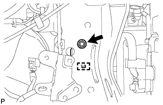
Install the front airbag sensor with the nut.
- Torque:
- 9.0 N*m { 92 kgf*cm, 80 in.*lbf }
-
Connect the airbag connector.
-
Check that the CPA is in the provisionally locked state.
-
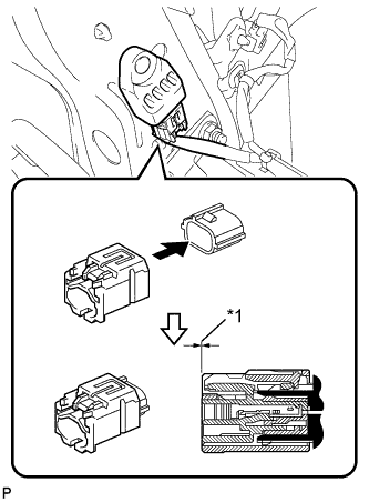
Text in Illustration *1 Conform Push the CPA until it makes a click sound.
Note
-
Engage the connector by pushing it straight.
-
Hold the CPA when engaging the connector.
-
Do not engage the CPA while pressing the CPA upper portion, because otherwise, the half connection prevention mechanism will not function.
-
-
Confirm that the rear side of the housing and the CPA rear surface are tightly fitted together.
-
-
Confirm that there is no looseness by shaking the front airbag sensor.
-
-
INSTALL NO. 2 RADIATOR SIDE AIR SEAL
-
Engage the 2 claws and install the radiator side air seal.
-
-
INSTALL NO. 1 RADIATOR SIDE AIR SEAL
Tech Tips
Use the same procedure as for the LH side.
-
INSTALL FRONT BUMPER ENERGY ABSORBER
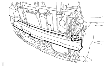
-
Engage the 2 guide and install the front bumper energy absorber.
-
-
INSTALL UPPER RADIATOR SUPPORT ABSORBER
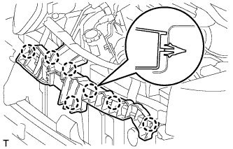
-
Engage the 7 claws and install the radiator support upper absorber.
-
-
INSTALL FRONT BUMPER COVER
-
Engage the 6 claws and install the front bumper cover.
-
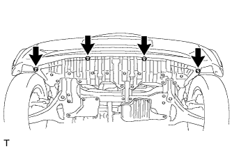
Tighten the 4 screws.
-
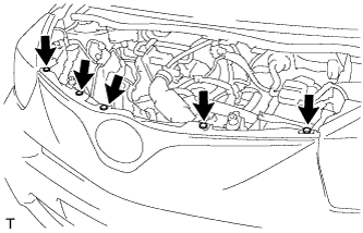
Install the 5 clips.
-
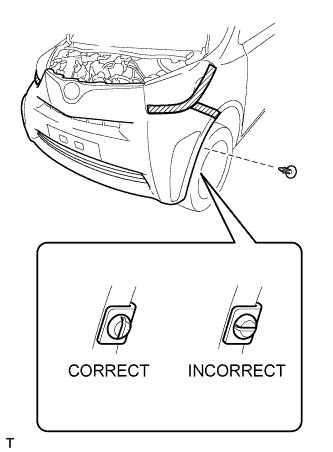
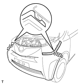
Install the pin hold clip.
Note
Insert the pin hold clip with the slot aligned vertically. Do not rotate the clip after inserting it. After installation, confirm that the slot is vertically.
Tech Tips
Use the same procedure for the RH and LH sides.
-
-
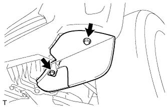
INSTALL FRONT WHEEL OPENING EXTENSION PAD LH
-
Install the front wheel opening extension pad with the 2 screws.
-
-
INSTALL FRONT WHEEL OPENING EXTENSION PAD RH
Tech Tips
Use the same procedure as for the LH side.
-
INSTALL AIR CLEANER CASE SUB-ASSEMBLY (for 1ND-TV)
-
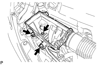
Install the air cleaner case with the 3 bolts.
- Torque:
- 7.5 N*m { 76 kgf*cm, 66 in.*lbf }
-
-
INSTALL AIR CLEANER FILTER ELEMENT SUB-ASSEMBLY (for 1ND-TV)
-
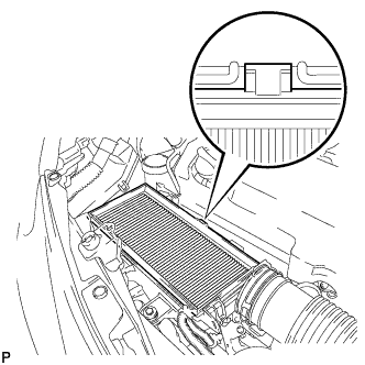
Install the air cleaner filter element.
Note
Engage the air cleaner filter element protrusion with the air cleaner case groove.
-
-
INSTALL AIR CLEANER CAP SUB-ASSEMBLY (for 1ND-TV)
-
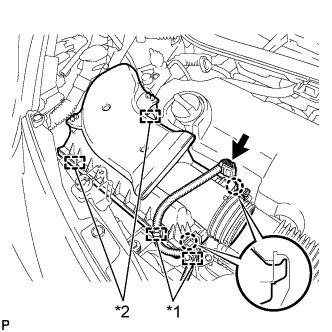
Engage the 2 claws and 2 clamps and install the air cleaner cap.
-
Connect the connector and 2 wire harness clamps.
Text in Illustration *1 Wire harness clamp *2 Clamp -
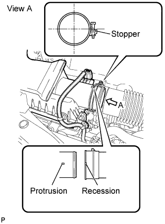
Connect the air cleaner hose to the air cleaner cap.
Tech Tips
-
The clamp should contact the air cleaner hose stopper.
-
Make sure that the air cleaner hose recession is securely engaged with the air cleaner cap protrusion.
-
-
-
CONNECT CABLE TO NEGATIVE BATTERY TERMINAL
- Torque:
- 5.4 N*m { 55 kgf*cm, 48 in.*lbf }
-
INSPECT SRS WARNING LIGHT
-
Inspect SRS warning light Click here.
-