AIRBAG SYSTEM, Diagnostic DTC:B1651/33

| DTC Code | DTC Name |
|---|---|
| B1651/33 | Manual Cut off Switch Trouble |
DESCRIPTION
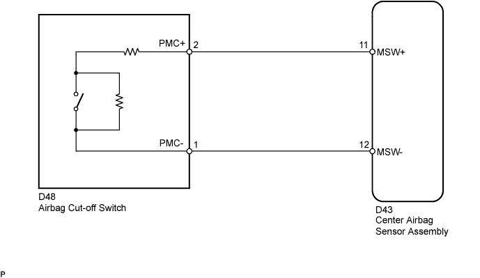
The passenger airbag manual cut-off switch circuit consists of parts including the center airbag sensor assembly and the airbag cut-off switch.
DTC B1651/33 is set when a malfunction is detected in the airbag cut-off switch circuit.
| DTC No. | DTC Detection Condition | Trouble Area |
|---|---|---|
| B1651/33 |
|
|
WIRING DIAGRAM
INSPECTION PROCEDURE
PROCEDURE
-
CHECK CONNECTION OF CONNECTORS
-
Turn the ignition switch off.
-
Disconnect the negative (-) terminal cable from the battery, and wait for at least 90 seconds.
-
Check that the connectors are properly connected to the center airbag sensor assembly and the airbag cut-off switch.
OK The connectors are properly connected.
NG 
CONNECT CONNECTORS PROPERLY
OK 
-
-
CHECK CONNECTORS
-
Disconnect the connectors from the center airbag sensor assembly and airbag cut-off switch.
-
Check that the connectors (on the center airbag sensor assembly side and airbag cut-off switch side) are not damaged.
OK The connectors are not deformed or damaged.
NG
REPLACE INSTRUMENT PANEL WIRE
OK
-
-
CHECK AIRBAG CUT-OFF SWITCH
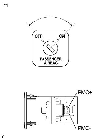
Text in Illustration *1 Component without harness connected
(Airbag Cut-off Switch)
-
Disconnect the connector from the airbag cut-off switch.
-
Measure the resistance according to the value(s) in the table below.
Standard Resistance Tester Connection Switch Condition Specified Condition D48-1 (PMC-) -
D48-2 (PMC+)
OFF 80 to 120 Ω D48-1 (PMC-) -
D48-2 (PMC+)
ON 320 to 480 Ω
NG
REPLACE AIRBAG CUT-OFF SWITCH Click here
OK
-
-
CHECK INSTRUMENT PANEL WIRE (CENTER AIRBAG SENSOR - AIRBAG CUT-OFF SWITCH)
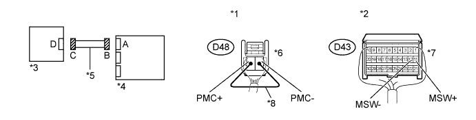
Text in Illustration *1 Rear view of wire harness connector
(to Airbag Cut-off Switch)
*5 Instrument Panel Wire *2 Rear view of wire harness connector
(to Center Airbag Sensor Assembly)
*6 Connector C *3 Airbag Cut-off Switch *7 Connector B *4 Center Airbag Sensor Assembly *8 Service Wire
-
Disconnect the instrument panel wire connector from the center airbag sensor assembly.
-
Connect the cable to the negative battery terminal, and wait for at least 2 seconds.
-
Turn the ignition switch to ON.
-
Measure the voltage according to the value(s) in the table below.
Standard Voltage Tester Connection Switch Condition Specified Condition D43-11 (MSW+) - Body ground Ignition switch ON Below 1 V D43-12 (MSW-) - Body ground Ignition switch ON Below 1 V -
Turn the ignition switch off.
-
Disconnect the cable from the negative (-) battery terminal, and wait for at least 90 seconds.
-
Using a service wire, connect terminals 2 (PMC+) and 1 (PMC-) of connector C.
Note
Do not forcibly insert a service wire into the terminals of the connector when connecting the wire.
-
Measure the resistance according to the value(s) in the table below.
Standard Resistance Tester Connection Condition Specified Condition D43-11 (MSW+) - D43-12 (MSW-) Always Below 1 Ω -
Disconnect the service wire from connector C.
-
Measure the resistance according to the value(s) in the table below.
Standard Resistance Tester Connection Condition Specified Condition D43-11 (MSW+) - D43-12 (MSW-) Always 1 MΩ or higher D43-11 (MSW+) - Body ground Always 1 MΩ or higher D43-12 (MSW-) - Body ground Always 1 MΩ or higher
NG
REPLACE INSTRUMENT PANEL WIRE
OK
-
-
CHECK CENTER AIRBAG SENSOR ASSEMBLY
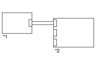
Text in Illustration *1 Airbag Cut-off Switch *2 Center Airbag Sensor Assembly
-
Connect the connectors to the center airbag sensor assembly and airbag cut-off switch.
-
Connect the negative (-) terminal cable to the battery, and wait for at least 2 seconds.
-
Turn the ignition switch to ON, and wait for at least 60 seconds.
-
Clear the DTCs stored in the memory Click here.
-
Turn the ignition switch off.
-
Turn the ignition switch to ON, and wait for at least 60 seconds.
-
Check for DTCs Click here.
OK DTC B1651/33 is not output. Tech Tips
DTCs other than B1651/33 may be output at this time, but they are not related to this check.
NG
REPLACE CENTER AIRBAG SENSOR ASSEMBLY Click here
OK 
USE SIMULATION METHOD TO CHECK Click here
-